Estimating the age of an electrical installation
Electrical testing alone is insufficient to give an installation’s exact age although, in some instances, it can assist. Instead, recognizing certain details will be a great skill which can be honed by experience.
Whilst appreciating that there is no substitute for time-served experience, the purpose of this article is to give some pointers to look out for in typical small/or medium-sized electrical installations.
It should of course be obvious that many installations will be comprised of components of differing ages – as installations often evolve and can be modified over time. Wiring accessories, switchgear, and light fittings, for example, are relatively easy to renew or replace (and often are). Wiring however, especially that concealed within the fabric of a building, is often left to serve successive updates to an installation.
Likewise, if a building is extended or partially modified and provided with an updated electrical installation in certain areas, often the remainder of the electrical installation may remain untouched. Many components within an electrical installation can deteriorate with age, giving rise to potential safety problems. Establishing the age of an installation and its components is therefore a crucial safety matter.
All these aspects need careful evaluation before making any conclusion as to an installation’s overall age. The older an installation is, the less common it becomes for it to remain totally in its original form.
Metrication of the construction industry
The British Standards Institution set a program for the metrication of the construction industry to take effect between 1969 and the end of 1972. Trade in British electric cables to metric standards began in January 1970.
To assist the industry in the transition, the logo shown in Figure 1 was often used between 1969 and 1975 on items that would contain incompatible differences between imperial and metric dimensions. This particularly applied to cables and items with screw threads. To this day, such legacy labels may still appear on things like trunking, conduits, and wiring accessory back boxes. Where spotted it is generally a very good indicator that the item was manufactured and probably first installed during the period 1969-1975.
Figure 1 - Metrication logo

Other distinguishing factors associated with the metrication process of electrical installations include:
Pre 1969/72:
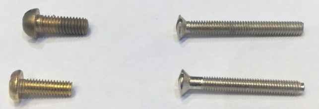
- Round head imperial 2BA sized screws used on round conduit boxes.
- Raised head imperial 4BA screws with no lead-in chamfer used for wiring accessory front plates.
1969/72 onwards:
- Pan head metric M4 sized screws used on round conduit boxes.
- Raised head metric M3.5 screws, often with a lead-in chamfer used for wiring accessory front plates.
Figure 2 - Common fixings screws (Imperial version shown on top with its metric counterpart beneath)
Wiring and cabling
Due to its often concealed nature and relative difficulty and cost to replace, wiring may often form the oldest component of many installations.
Wiring type, conductor size, construction, sheath markings and identification colour of insulation are all factors that can prove revealing when scrutinized. Although the industry uses many different types of cable, focus will be made on the more common types.
Knowledge of cable manufacturers, that have come and gone, as well as trade names can reveal even more, although this topic is beyond the scope of this article.
Rubber insulated fixed wiring cable
This was in widespread use within the construction industry for general purpose installation work until the early 1950s. During that decade its usage sharply declined, in favour of thermoplastic insulation such as polythene (polyethylene) and, later, polyvinylchloride (PVC).
Whilst now it is increasingly rare to encounter rubber insulated cable still in service for general fixed wiring work, such cabling exhibits characteristics that make it easy to identify.
The two most common types were:
1. Rubber insulated & sheathed multicore cabling. These often have a dull black outer black sheath, usually now hardened and sometimes brittle. They were referred to as ‘TRS’ (tough rubber sheath) or sometimes ‘CTS’ (cab tyre sheathed) cabling.
2. Single core cables, often with a hemp type braided outer layer, usually coloured black or dull red. These are generally referred to as ‘VRI’ (vulcanized rubber insulated). They will often be found run within metal conduits, oval ‘slip tubes’, metal trunking or wooden capping. Occasionally they may be encountered unenclosed in building voids. Some cables of this type may also contain asbestos. Guidance for electricians dealing with asbestos can be found in Michael Peace’s July 2020 article. Usage of the larger sizes of VRI cables continued into the 1960s for applications such as meter tails.
Thermoplastic insulated fixed wiring cable
The construction industry embraced this type of cable from the early 1950s onwards. During that decade it quickly began to supersede rubber insulated cabling for general applications. The earliest variety used polythene insulation, characterized by its shiny appearance and slippery feel, these characteristics are still often evident decades on. Later cabling used PVC insulation and in recent years some cabling used may be low smoke halogen free (LSHF) which are usually much stiffer and more difficult to strip back.
Whilst the timespan of its usage and relative longevity can often make estimation of its age difficult, key factors that may help include:
1950s to 2004-06:
- Red and black line & neutral conductor identification for single phase installations.
1950s to late 1960s:
- Imperial sized conductors, usually of tinned copper stranded construction.
- ‘BS 2004’ sometimes marked on sheath.
1950s to early 1960s:
- Polythene cables produced by some manufacturers with characteristic shiny outer sheath and conductor insulation.
1950s – early 1970s:
- Insulated CPC sleeving on flat insulated & sheathed cables rarely used and many cables did not even incorporate an integral CPC.
Early 1960s onwards:
- Polythene insulation superseded in favour of PVC by most manufacturers.
1966 onwards:
- Wiring regulations from this point onwards required a CPC at all points in all circuits.
1950s to late 1960s:
- Metal ‘buckle type’ clips in common use with sheathed cables.
1967 – 1970:
- Many manufacturers gradually replaced tinned copper conductors in PVC cables with untinned copper.
Late 1960s onwards:
- Plastic clips introduced – often with the cable size marked on them.
1966 – 1977:
- Green coloured identification of protective conductors and if used, sleeving.
1968 – 1975:
- Certain PVC cables from this era with untinned conductors subsequently found to be susceptible to long term, slow chemical degradation with what became known as ‘green goo’ exuding at terminals. This was often encountered beneath vertical drops in warm indoor locations.
More information on this phenomenon can be found in this Wiring Matters article.
1969-72 onwards:
- Metric sizing replaced imperial, with untinned conductors and solid cores on sizes up to and including 2.5 mm2.
- ‘BS 6004’ marking often on sheath (usually grey in colour or sometimes white).
1972-1976:
- Solid cored aluminum or copper-clad aluminum conductors made available due to world-wide copper supply crisis.
Late 1970s onwards:
- Where applicable, ‘BASEC’ marking appeared on outer sheath of cables, but only on those that had undergone the BASEC independent third-party certification.
1978 onwards:
- Sole use of green/yellow bi-coloured identification required for protective conductors.
1969-72 to 1981:
- 2.5 mm2 flat PVC/PVC sheathed cables manufactured with 1.0 mm2 CPC.
1981 onwards:
- 2.5 mm2 flat PVC/PVC sheathed cables had CPC enlarged to 1.5 mm2.
Mid 1990s onwards:
- Practice of showing production date and conductor size marking on outer cable sheaths was adopted by some manufacturers.
1995 onwards:
- CE marking introduced in the UK and may be evident on some cables.
2004-06 onwards:
- Brown and blue line and neutral conductor identification introduced for fixed wiring, replacing former red and black as part of harmonization process.
- Grey coloured sheath now almost exclusively used on PVC cables.
- White coloured sheath now used to signify LSHF type cables.
2015 onwards:
- Metal fixing clips became necessary in some installation conditions; to guard against cable collapse during a fire and associated entanglement hazards.
PVC insulated and sheathed flexible cables
Flexible PVC cables (often just referred to as ‘flex’ or previously ‘cords’) generally tracked many of the developments in fixed wiring cabling, but note the much earlier conductor insulation colour change transition:
Mid 1950s onwards:
- Commercial usage became popular, gradually replacing rubber insulated and sheathed or rubber and hemp braided cables.
1950s to late 1960s:
- Imperial sized conductors in use, often of tinned copper.
1969-72 onwards:
- Metric sized conductors introduced, often of untinned copper.
1950s to 1971:
- Conductor insulation was coloured red, black and green for general purpose three core flexes.
1971 onwards:
- Requirement for conductor insulation coloured brown, blue and green/yellow.
1950s – 1974:
- Unsheathed flexible cable permitted for applications such as pendant drops.
1974 onwards:
- Sheathed flexible cables required if operating at above extra-low voltage.
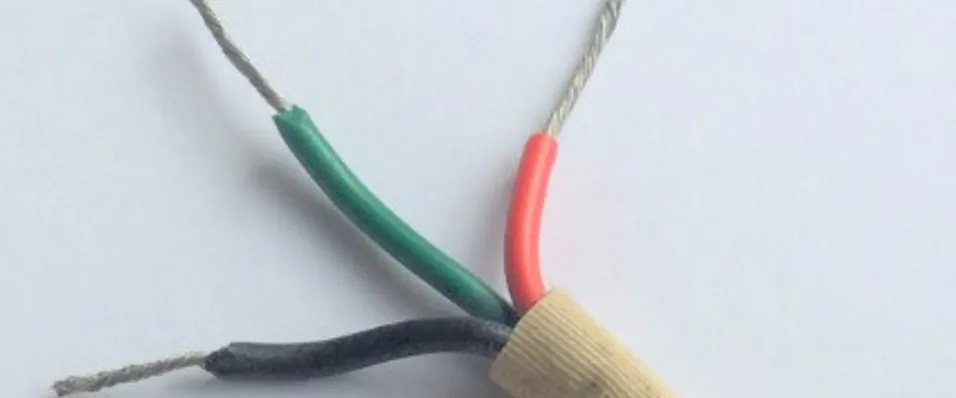
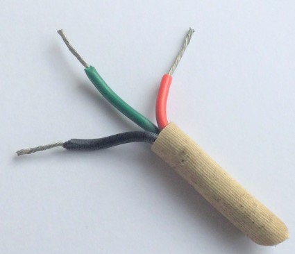
Figure 3 - Typical pre-1971 flex (note colours and tinned conductors)
Mineral insulated cabling
This cable became popular from the early 1950s onwards, although it had been in existence for many years prior. It offered very small outside diameter for a given current carrying capacity, good mechanical strength and of course, excellent fire resistance.
It enjoyed fairly extensive usage in the construction industry up until the late 1970s, particularly for external cabling, use in boiler rooms, churches and of course in fire alarm systems/safety system circuits. A single core special cable of this type was often used for electric underfloor heating.
Usage declined rapidly from the early 1980s with the introduction of pliable fire rated cables which offered faster installation time, a need for less skilled installation techniques and lower costs.
Typical signs to look for include:
Early 1950s onwards:
- Bare copper outer sheathed cables prevalent with occasionally black thermoplastic outer covering.
Mid 1960s to mid-1980s:
- Orange coloured outer covering in common use.
Mid 1980s onwards:
- Usage in steady decline, but where still used – predominantly on safety circuits, red outer covering became common.
1950s – 1969/72:
- Imperial gland size notation using a three digit number such as ‘234’.
1969/72 onwards:
- Metric gland size notation, using coding such as ‘2L 2.5’.
Wiring accessories
Although wiring accessories can be updated relatively easily, their age can mask older wiring behind. Caution should therefore be taken in this respect if using this factor alone to establish an installation’s age. Changes to the relevant product standard to which wiring accessories are made and often marked, as well as manufacturing material and styling fashions, are all useful to assist in estimating their age.
In-depth knowledge of a particular manufacturer’s production changes is also extremely useful – although this information is beyond the scope of this article.
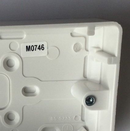
Additionally, with the advent of manufacturers working under Quality Assurance regimes requiring traceability in the late 1980s onwards, wiring accessories often carry some sort of production date. Where found, either as characters printed on the item, moulded into its material, or sometimes a stick-on label, a date or code can be found – sometimes explicitly showing a date.
Other useful generic age-distinguishing factors for wiring accessories include:
1920s – mid 1960s
- Wooden mounting blocks for accessories such as light switches in common use.
1930s – mid 1960s
- Brown coloured thermosetting plastic ‘Bakelite’ used in many manufacturers’ ranges.
Mid 1960s – early 1970s:
- Flush metal back boxes for light switches often had insulating plastic insert lugs for faceplate fixing screws - to overcome safety issues arising from lack of CPCs in some cables.
Late 1950s – 1972/3:
- Ivory coloured thermosetting plastic used by many manufacturers.
1972/1973 onwards:
- White coloured thermosetting plastic introduced and quickly adopted by the majority of wiring accessory manufacturers.
1975 onwards:
- Twin 13 A BS 1363 sockets using four front plate fixing screws discontinued production.
Late 1980s onwards:
- Woodscrews used often for fixing accessory back boxes, changed from slotted to cross head design, due to rising popularity of powered screwdrivers.
Figure 4 - Date coding on a wiring accessory showing week 37 of 2005
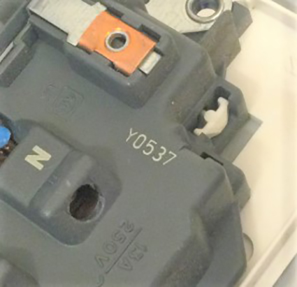
Figure 5 - Date coding on a wiring accessory showing week 46 of 2007
Lighting and luminaires
As luminaires, like wiring accessories are easily replaced, they can mask an older installation.
Changes and development in lamp technology, compliance with lighting design guidance as well as styling cues can all assist in determining the age of a lighting installation however, information found relatively easily within such luminaires can often give more exact information. As with wiring accessories and switchgear, date codes can often be found inside luminaires.
Whilst in more recent years, production dating for traceability of manufacture will often be encountered in many luminaires, dating capacitors used in association with some lighting control gear is a practice that goes back to the 1940s.
The following gives some milestones in the development of lighting technology:
1940s – late 1970s:
- 38 mm (T12) lamps common for linear fluorescent lighting.
Early 1980s onwards:
- 25 mm (T8) linear fluorescent lamps introduced for all sizes except the 2,400 mm length.
Early 1980s onwards:
- Compact fluorescent lamps introduced.
Mid 1980s onwards:
- Metal louvred luminaires in extensive use for VDU and office lighting.
Mid 1980s onwards:
- Electronic control gear began to replace wire-wound components in fluorescent and discharge luminaires.
Mid 1990s onwards:
- 16 mm (T5) longer linear fluorescent lamps introduced.
Late 1990s onwards:
- VDU and office lighting designs incorporated more measures to illuminate ceilings and upper walls as VDU screen technology developed.
2010 onwards:
- LED lighting saw rapid development and take-up in the industry
Switchgear and distribution boards
As with wiring accessories and luminaires, switchgear such as distribution boards or consumer units are often an easy replacement and can mask an older installation.
Successive changes to the requirements set out in BS 7671 and earlier editions of the Wiring Regulations was generally the main driver behind distribution switchgear getting renewed, closely followed by the need for more circuits to be added to an existing installation.
As with wiring accessories, an in-depth knowledge of a particular manufacturer’s production changes is also extremely useful; although again this information is beyond the scope of this article.
As with wiring accessories and switchgear, date codes can often be found on or within switchgear. In the case of larger industrial or commercial switchgear, a serial number and manufacturer’s unique referencing can often lead to an exact date of manufacture.
Other useful generic age-distinguishing factors of note include:
1920s – mid 1980s:
- Re-wireable fuses frequently found many installations, particularly domestic dwellings.
1950s – early 1980s:
- Cartridge HRC (often to BS 88) fuses frequently found in commercial and industrial installations, and occasionally (to BS 1361) within consumer units in dwellings.
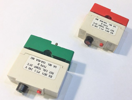
Mid 1960s onwards:
- Miniature circuit breakers (MCBs) became widespread in commercial installations. Uptake in domestic installations followed from the 1980s onwards.
1965 – 1988/89:
- MCBs manufactured to BS 3871.
1950s to 1981
- Voltage operated earth leakage circuit breakers in common use within TT-earthed installations.
1981 onwards:
- Current operated earth leakage circuit breakers (RCDs) usage began to supersede voltage operated types.
1988/89 onwards:
- Circuit breakers to BS EN 60898 introduced.
1990 onwards:
- Successive editions of BS 7671 recognized increasing use of RCDs for ‘additional protection’ requirements.
2015 onwards:
- Metal consumer units introduced by BS 7671 for use in dwellings.
Figure 6 - Current operated earth leakage circuit breaker (RCD) of a style in widespread use during the 1980s
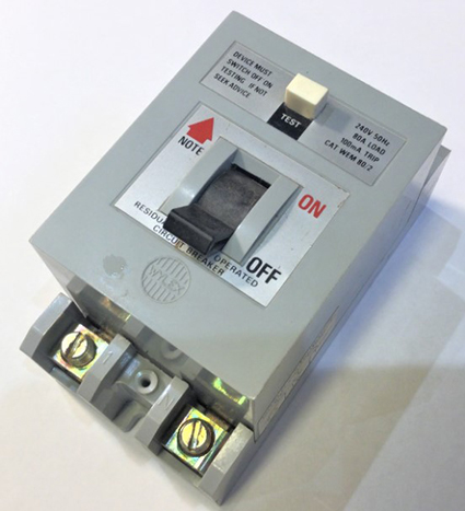
Figure 7 - BS 3871 plug-in miniature circuit breaker of a style produced from the late 1960s to 1985
Conclusions
Unless detailed, dated documentation exists, it will be difficult to establish an exact age for any installation. This dilemma may be compounded, particularly with larger and/or older installations incorporating sections and components of different ages. The possibility of equipment having been installed that was not new at the time should always be considered - particularly in domestic premises.
Notwithstanding this, by compiling findings from an installation inspection against some of the information highlighted, it is often found that different factors will ‘fit’ like jigsaw pieces and a reasonably accurate assessment of age can usually be made.