
Broken PEN
What is a PEN conductor?
A protective earthed neutral (PEN) conductor is a single conductor that has the combined function of providing the neutral and protective earth conductor in a TN-C-S earthing arrangement.
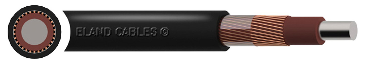
A PEN conductor is normally, but not exclusively, used with an LV PME supply service earthing system. The conductor can be either separate from the line conductors as with an overhead line service or combined in a multi-core cable in the form of a number of conductors wound around the line conductors to form the armouring, as in a concentric cable. The copper armouring of the concentric cable indicated in Figure 1 is the PEN conductor.
Figure 1: Concentric cable
If the supply cable has a separate protective conductor, is it TN-S?
Due to the nature of a PME earthing arrangement, distributors should not mix TN-C-S and TN-S earthing arrangements on the same network. However, when repairs or alterations are made to the distribution network, sometimes damaged 4-core cables can be replaced with 3-core.
It is sometimes assumed that if a supply cable has a separate protective conductor, the installation has a TN-S earthing arrangement. This is not necessarily correct; if it is supplied from a distribution network the installer should presume it is a TN-C-S, unless it is confirmed by the Distribution Network Operator (DNO) in writing to be a TN-S earthing arrangement.
What is a PME earthing arrangement?
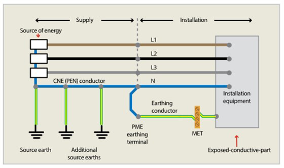
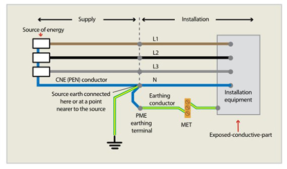
A protective multiple earthing (PME) arrangement is a form of TN-C-S, as seen in Figure 3. It refers to the earthing arrangement provided by the distributor where it terminates in the cut-out at the origin of the consumers TN-C-S installation.
‘Multiple’ in PME means there could be multiple earth electrodes installed along the cable route to ensure the resistance of the PEN conductor to Earth is within the values required by the DNO, ENA Engineering Recommendation G12/4 states 20 ohms.
The ‘S’ refers to separation of the neutral and earth on the installation side. The star point is earthed by the distributor, usually in the spill box of the transformer, as seen in Figure 2.
Figure 2: Transformer neutral to Earth connection inside transformer spill box
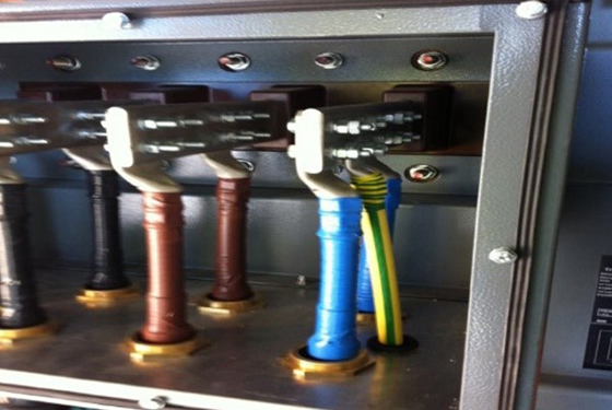
Figure 3: TN-C-S system with PME
What is a PNB earthing arrangement?
A protective neutral bonding (PNB) arrangement is also a form of TN-C-S and may be used depending on individual DNO requirements. The PEN or CNE conductor is connected to one point only, remote from the transformer, between the transformer and the supply terminals of the consumer.
ENA Engineering Recommendation G12/4 recommends that the distance between the connection to Earth and the consumers intake shall be 40 m or less, however in order to minimise the risk of voltage rise in the event of a broken neutral this connection should be made as close as practicable to the consumers supply terminals. This is usually located within the customers LV switchboard, along with the neutral earth link, see Figure 4. However, note that the neutral and Earth are separated on the consumers side of the installation.
Figure 4: Neutral – Earth link in customers LV switchboard
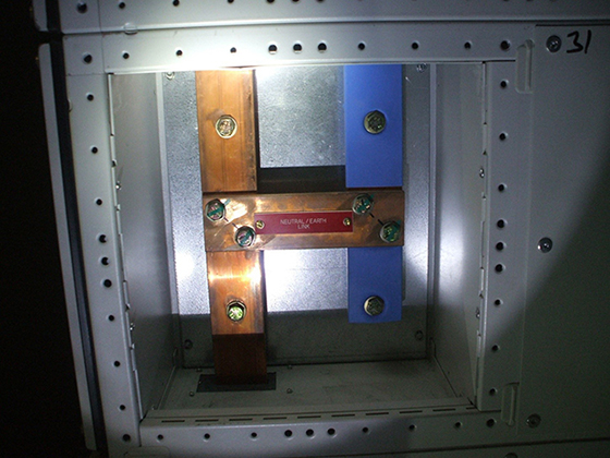
Figure 5: IET Guidance Note 8 TN-C-S system with PNB
What are the responsibilities of the distributor for PME?
Electrical distributions are governed by the Electrical Safety Quality and Continuity Regulations (ESQCR) 2002 (as amended), which is a statutory instrument. The Energy Networks Association (ENA) provides guidance to distributors in their Engineering Recommendation G12 issue 4, Requirements for the application of protective multiple earthing to low voltage networks.
ESQCR prevents distributors from providing a PME earth terminal for certain installations, such as the metalwork in a caravan or boat and fuel filling stations. Although, if part of a larger site, PME facilities may be provided for the permanent buildings, provided the independent earthing arrangement is segregated from the PME.
What are the requirements of BS 7671:2018+A1:2020 for PME systems?
The requirements of ESQCR are repeated in BS 7671:2018+A1:2020, in the following Sections:
- Section 708 - Electrical installations in caravan/camping parks
- Section 709 - Marinas and similar locations
- Section 730 - Onshore units of electrical shore connections for inland navigation vessels
- Section 740 - Temporary electrical installations for structures, amusement devices and booths at fairgrounds, amusement parks and circuses.
Installations which may be allowed a PME earthing arrangement, but special precautions must be taken, include:
- Section 702 - Swimming pools and other basins
- Section 704 - Construction and demolition site installations
- Section 705 - Agricultural and horticultural premises
- Section 711 - Exhibitions, shows and stands
- Section 717 - Mobile or transportable units.
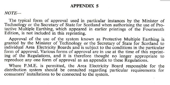
When the 14th Edition of the IEE Wiring Regulations was published in 1966, Appendix 5 acknowledged the introduction of PME earthing systems, as shown in Figure 6.
Figure 6: Appendix 5 of 14th Edition IEE Wiring Regulations
A note was added to Regulation 411.4.2 in BS 7671:2008+A3:2015 which states, ‘The PE and PEN conductors may additionally be connected to Earth, such as at the point of entry into the building.’, as it is acceptable under Electricity Safety, Quality and Continuity Regulations (ESQCR), but prior to this under the ‘Supply Regulations 1988’ it was not acceptable for the customer to Earth the DNO neutral.
Regulation 543.4 of BS 7671:2018+A1:2020 sets out the requirements for combined protective and neutral (PEN) conductors. A note states that ‘Regulation 8(4) of the ESQCR prohibits the use of PEN conductors in consumers’ installations.’
Amendment 1 to BS 7671:2018 was published in February 2020, the Amendment applied only to Section 722, which is for electric vehicle charging. The main change in this Amendment is the inclusion of additional methods of protection against open-circuit PEN conductors for electric vehicle charging installations, using devices that detect under- or over-voltages on the distribution network.
The requirements for protective bonding of installations with a PME earthing arrangement are identified in Table 54.8 of BS 7671:2018+A1:2020. The requirements are more onerous than for TN-S systems, in order to withstand any diverted neutral currents which may exist, due to an open-circuit PEN conductor.
Interestingly, Regulation 114.1 of BS 7671:2018+A1:2020 states that for a supply provided in accordance with the Electricity Safety, Quality and Continuity Regulations (ESQCR), ‘it shall be deemed that the connection with Earth of the neutral of the supply is permanent.’
Whilst an open-circuit PEN conductor occurs on the distribution network, the consequences can have serious effects on the consumers electrical installation. Each installation should be assessed individually, and if the risk of a person coming into contact with conductive parts connected to the PME earthing arrangement and Earth, is not acceptable, additional protective measures must be taken.
What are the issues with PME?
In the event of the distributor’s PEN conductor becoming broken (open-circuit), diverted neutral currents and dangerous touch voltages can appear on any metalwork connected to the Main Earthing Terminal (MET) of the installation.
The risk of electric shock is increased for persons outdoors, as they are likely to be in contact with Earth, possibly even barefooted, which would lower the body resistance to Earth and increase the touch current.
Examples of areas of risk would include outside water taps and Class I electrical equipment connected to the MET. Fire can also be a risk due to the heating effect of extraneous-conductive-parts, such as water and gas pipes caused by the diverted neutral current.
Further information can be found in IEC 60479-1:2018 Effects of current on human beings and livestock and IEC/TR 60479-5 Touch voltage threshold values for physiological effects.
What voltages can appear on PME earthed metalwork under open-circuit PEN conditions?
Under open-circuit PEN conditions, the voltage between the neutral and Earth will depend on the ratio of the balance of load on the distribution network. In some cases, this can be up to 230 V. This becomes more complex when power factor is taken into consideration. For the purposes of this article, power factor has not been considered.
Kirchoff’s Law states that the sum of currents flowing into a node is equal to the sum of currents flowing out of the node. In a three-phase distribution system the common neutral connection is the star point.
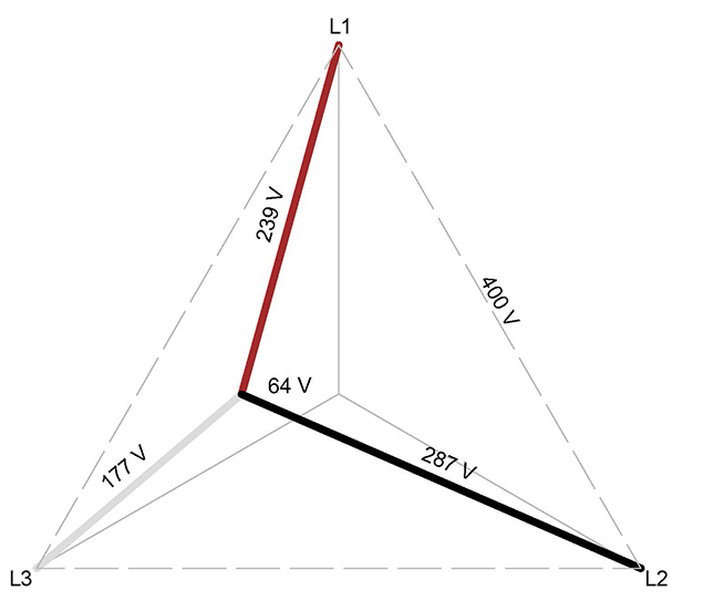
If the load is not balanced, a current will flow in the neutral conductor, this will be a phasor sum of the line currents. If the PEN conductor becomes open-circuit, the neutral current cannot flow. The voltages between line and neutral ‘shift’ until a balance point is reached eliminating the need for a neutral current. The star point is said to 'float' to a position that achieves balance.
This is illustrated on the phasor diagram in Figure 7. The distance from the centre point of the triangle to the displaced star point of the three-phases indicates the touch voltage to Earth; 64 V. The star point having moved towards the heaviest loaded phase, in this case, L3.
Figure 7: Phasor diagram
This condition will cause an overvoltage in some phases and undervoltage in others and is likely to cause equipment not designed to operate at either over- or under-voltage to malfunction or be damaged. It is a dynamic situation as equipment installed on the affected phase malfunctions will also affect the load demand and balance of the network and thus the voltage to Earth also changes.
Regulation 442.3 of BS 7671:2018+A1:2020 provides information regarding the power frequency stress voltage, in the event of loss of the neutral conductor in a TN or TT system.
Three-phase balanced network
In a three-phase balanced network there is no neutral current, where there are no triple harmonics. However, it should be remembered that any electrical installation comprising several single-phase loads is unlikely to be or remain balanced for a period of time.
It should also be remembered that the voltage to Earth will depend on the ratio of balance on the distribution network and not just the consumers installation.
Scenario 1 Normal operating conditions
Under normal operating conditions, the current path returns from each property via the PEN conductor to the distribution transformer, in such conditions there is no voltage between PME neutral and Earth.
Scenario 2 Open-circuit PEN conductor in single-phase section of cable
In the event of an open-circuit PEN conductor on the single-phase section of cable, the return path is via the extraneous-conductive-part, such as a metallic water pipe shared with an adjacent installation. This will cause a touch voltage between any connected exposed- and extraneous-conductive-parts to Earth, the voltage will vary according to the resistance of the return path.
Scenario 3 Open-circuit PEN conductor in three-phase section of cable
If the PEN conductor breaks in a section of three-phase cable, the return path will be via the adjacent installation, back to the L2 phase. This means that up to 400 V could exist within the single-phase installation. The voltage to Earth will be higher if the distribution network is unbalanced.
In the real world, the situation is likely to be much more complex with many variables affecting the level of touch voltage and diverted neutral current. It is possible that the combined neutral currents for several installations could return via one installation.
This situation, which can be difficult to detect, results in a voltage to Earth of up to 230 V and a voltage between live conductors up to 400 V present at any point in those installations that are affected by the break in the neutral conductor.
What precautions can be taken to limit the rise in voltage on the consumer’s earth terminal in the event of an open-circuit PEN conductor?
If the consequences of an open-circuit PEN conductor pose an unacceptable risk, additional protective measures should be taken; but let’s take a look at the practicalities.
Additional Earth electrode
A method of protection that can mitigate the effect of an open-circuit PEN conductor is the connection of an additional earth electrode with a suitably low resistance value to keep the touch voltage below a value deemed acceptable by the designer. The resistance value required can be calculated according to the load of the installation with the following equation:
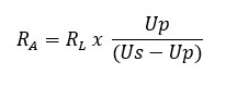
Table 14.1: IET Guidance Note 5 Protection against electric shock
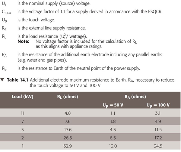
Table 14.1, extracted from The IET’s Guidance Note 5 Protection against electric shock, provides typical values of resistance required to reduce touch voltages to 50 V and 100 V respectively. In practice and depending on load requirements, these resistance values can be difficult to achieve with an earth electrode and will likely require specialist earthing arrangements to be installed, such as earth mats. For example, for an electrical installation with a maximum demand of 7 kW, an earth electrode with a value of 2.1 ohms would be required to keep the touch voltage below 50 volts.
In the Highway’s sector when installing street furniture, such as street lighting, traffic lights and road signs connected to a PME earthing arrangement, it is common practice to install an additional earth electrode usually at the feeder pillar and the final column on the circuit.
Further information on calculating the resistance of additional earth electrodes can be found in IET Guidance Note 5, protection against electric shock.
TT Earthing arrangement
If the risk of an open-circuit PEN conductor is not acceptable, TT Earthing arrangements are a reliable and effective method. An earth electrode can be installed to create a TT earthing arrangement, either for part of or for the whole installation. BS 7671:2018+A1:2020 generally requires a resistance value of less than 200 ohms, with RCDs installed to provide fault protection. However, installing a TT earthing arrangement does not come without risk, care should be taken to avoid striking buried underground services, such as cables and pipes. Service location drawings will be required to determine the location of existing underground services.
It is also important to ensure requirements are adhered to with respect to minimum separation distance from other earthing systems or buried conductive parts connected to other earthing systems. This is to prevent voltages appearing on the TT earthing arrangement in the event of an open-circuit PEN conductor fault. DNOs have their own requirements, so it is important to check.
Further information can be found in BS 7430:2011+A1:2015 Code of practice for protective earthing of electrical installations.
How do I know if an installation I am working on has an open-circuit PEN conductor?
Precautions should be taken before working on any installation to determine if any hazardous touch voltages exist on conductive parts before starting work, this is especially important when working outdoors and in contact with Earth.
It is especially important before disconnecting any earthing or protective bonding conductors to check there is not any diverted neutral current flowing. This can still happen even if the installation is isolated.
There is not one simple test to indicate if there is an open-circuit PEN conductor or not. There are many variables which will have an influence on the readings, such as the location of the break in the PEN conductor, the ratio of load of the network and if extraneous-conductive-parts are shared with other installations. However, the test methods below may give an indication if there is a problem.
As part of safe isolation procedure, a test to indicate the presence of voltage must be carried out between conductors in the usual manner. A simple non-contact voltage indicating device, more commonly known as a ‘volt stick’, can also be used to detect voltage and without the need for a reference to Earth. It should be noted that a ‘standard’ non-contact voltage indicating device, used by most electricians, has an operating threshold in excess of 200 volts AC. Therefore, a touch voltage of 70 volts or more could go undetected and could cause injury. Single-pole voltage indicating devices are available in a variety of different voltages, some can detect voltages of 50 volts or less.
However, it is important to understand that using voltage detection only may not detect the presence of an open-circuit PEN conductor, if the diverted neutral current is returning through an alternate path. It is not until the earth conductor is disconnected, that the circuit is broken and the voltage can be detected and the pipework becomes live. This could be an extremely dangerous situation as there could be several amps flowing depending on the distribution network arrangement.
An indication of diverted neutral currents can be identified with a standard clamp ammeter by testing for a current flowing in the earthing conductor, when the installation is supplying a connected load, as seen in Figure 8. It could also be placed around the pipework within the installation to detect the presence of diverted neutral current.
Figure 8: Clamp ammeter
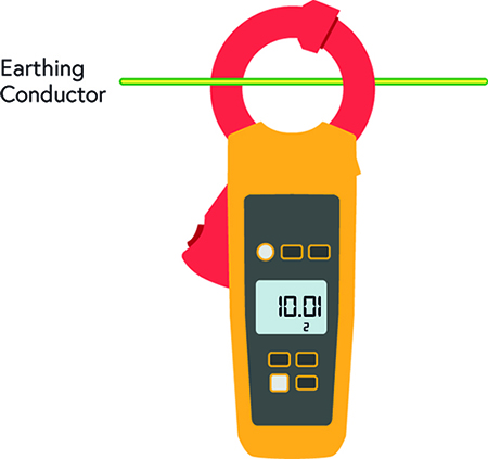
There may be some leakage current in the installation. Depending on the equipment installed, it is likely to be in the region of a few milliamps. Several amps flowing indicates an open-circuit PEN conductor problem.
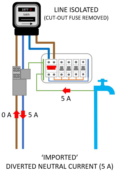
The location of the break in the neutral conductor will determine if the diverted neutral current is being ‘imported’ or ‘exported’ from the installation. If the current increases with the load of the installation, it indicates a broken PEN conductor on the installation as the neutral current is being ‘exported’, as seen in Figure 9. Whereas, if diverted neutral current can still be detected in the earthing conductor with the installation isolated, this would indicate diverted neutral current being ‘imported’ from other installation(s) on the distribution network, as seen in Figure 10.
Figure 9: Exported diverted neutral current
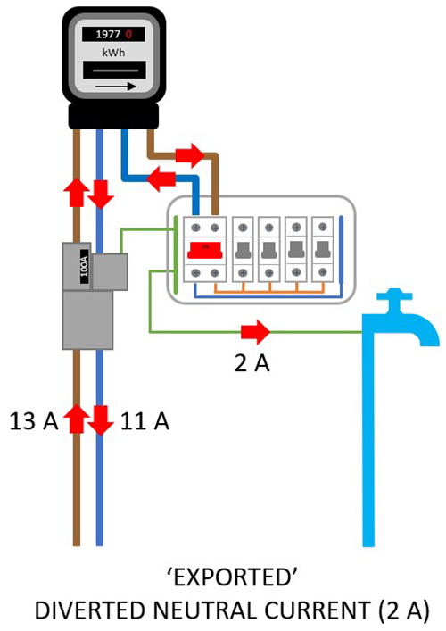
Figure 10: Imported neutral current
What do I do if I suspect an open-circuit PEN conductor?
Diverted neutral currents can cause fires and/or electric shock. When working on an installation, if an open-circuit PEN conductor is suspected, it must be reported to the electrical distributor immediately by telephone, using the emergency number 105. The call will be automatically directed to the local DNO’s emergency number for the area.
Summary
Whilst the issue of an open-circuit PEN conductor is the distributor’s responsibility, it could have serious consequences to the consumer’s electrical installation. Depending on the arrangements of the installation and the potential consequences, additional protective measures should be installed.
PME is suitable for many applications, but caution should be taken where contact with true Earth and PME earthed metalwork is possible.
In order to determine if additional protective measures are required, the designer will need to assess the risk.
Prior to commencing work, carry out testing to determine if conductive parts are live.
If an open-circuit PEN conductor is suspected, call 105 immediately to report an emergency to the local electrical distributor without delay.