Island mode earthing arrangements: New Guidance in the Second Edition of the IET Code of Practice on Electrical Energy Storage Systems
Introduction
The second edition of the IET Code of Practice for Electrical Energy Storage Systems was published in December 2020.
It builds on the first edition to provide the most up-to-date guidance to help support the growth of the electrical energy storage market.
It has been updated to take account of developments in the industry, progress in standardisation and address emerging technical challenges such as arc flash risk assessments.
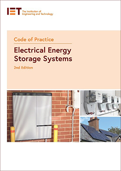
This article introduces the concept of prosumer’s electrical installations (PEIs) and operating modes for an electrical energy storage systems (EESS).
It then examines the earthing arrangements for island mode operation for PEIs with EESS.
EESS in PEIs
EESS mean that PEIs can continue to supply loads when the normal supply is interrupted.
EESS power conversion equipment (PCE) is typically connected either:
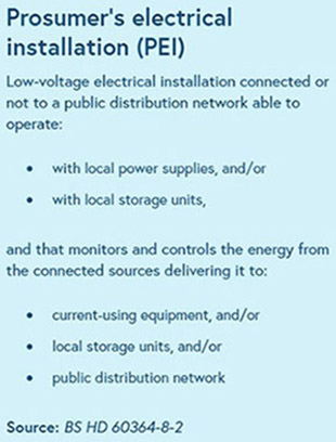
- on the DC side of the PCE for a local generation system, such as solar PV, as shown in Figure 1. This is termed DC coupling.
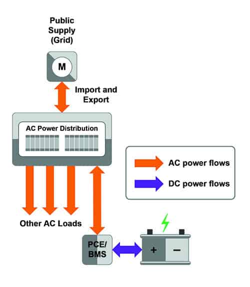
- in parallel with other loads, for example in the arrangement shown in Figure 2. This is termed AC coupling.
Unlike uninterruptible power supplies (UPS), EESS often operate in parallel with the grid supply, and power conditioning is not always guaranteed.
Figure 1: Example of DC coupled EESS
Figure 2: Example of AC coupled EESS
Modes of operation for EESS
Since EESS are effectively types of generator, Regulations 21 and 22 of the Electricity Safety, Quality and Continuity Regulations (ESQCR) guide the requirements for the basic modes of operation.
The modes of operation for EESS are:
- Connected mode, where the installation is connected to the grid. During connected mode, the installation may be direct feeding (importing power from the grid) or reverse feeding (exporting power to the grid).
- Island mode, where an electrical system normally connected to the grid is operating in a mode where some or all of the installation is isolated from the grid and is operating solely from an EESS. This is sometimes called “backup mode”.
In connected mode, an installation with EESS must comply with Regulation 22 of the ESQCR. The PCE must meet appropriate standards set out in ENA Engineering Recommendations G98 or G99 to avoid disrupting the operation of the grid, and respond to voltage and frequency fluctuations present on the grid. When the grid supply is lost, the PCE must be disconnected from the grid.
In island mode, an installation with EESS must comply with Regulation 21 of the ESQCR, and the PCE operates as a switched alternative to the grid. All live conductors, that is line(s) and neutral, that are to be powered in island mode must be disconnected from the grid. The installation may remain connected to the distributor’s means of earthing (where this is provided).
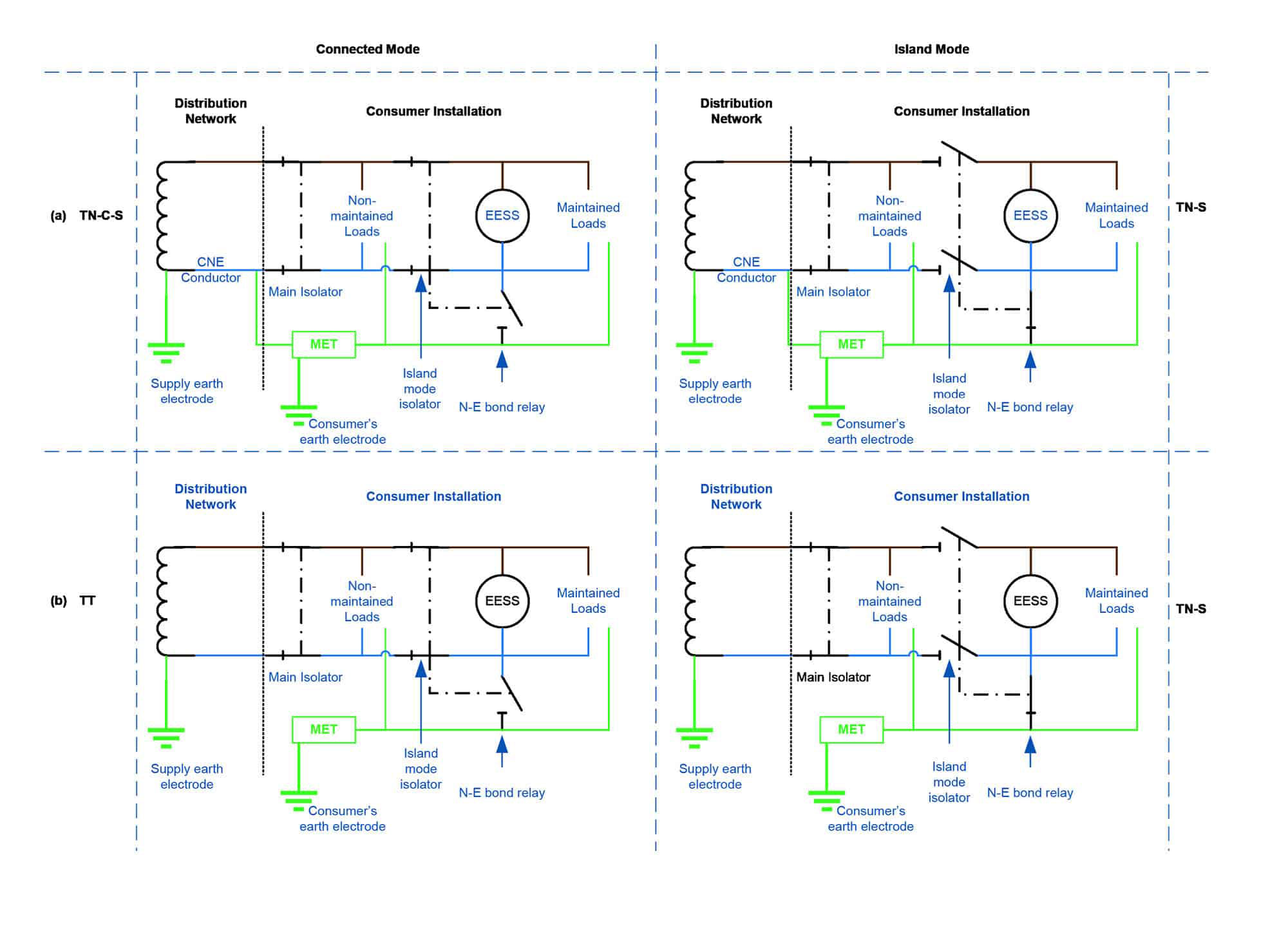
Earthing arrangements for island mode operation
In connected mode, an installation with a TN earthing arrangement (TN-C-S or TN-S) may use the distributor’s means of earthing. In a TT system, the consumer’s earth electrode is used – but care needs to be taken to ensure that this provides an earth of sufficient quality.
However, when the installation moves to island mode, it is important to make special earthing provisions.
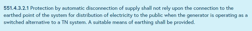
Regulation 551.4.3.2.1 of BS 7671 states that, in TN systems, generators operating as a switched alternative to the public supply cannot continue to rely on the distributor’s means of earthing.
In systems where a low voltage supply is provided to the installation, the neutral of the supply is earthed at the distributor’s transformer.
Accordingly, in systems operating in island mode, the distributor’s neutral-earth link cannot and must not be relied upon, as this is switched out when the live conductors are disconnected.
An installation that operates in island mode therefore requires:
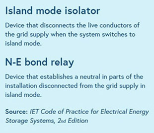
- a switching mechanism to disconnect live conductors of the installation that are to be powered in island mode from the grid. The IET Code of Practice for Electrical Energy Storage Systems calls this an island mode isolator
- a switching mechanism to provide a neutral for the island mode The IET Code of Practice for Electrical Energy Storage Systems calls this an N-E bond relay, and
- a consumer earth electrode. In TT systems, this may be the TT system consumer electrode, if it meets specific technical requirements.
The earthing arrangement of most EESS in island mode, where the installation has a low voltage public supply connection, is therefore always TN-S.
Note: If the N-E bond relay were not present, and the EESS inverter has a permanent connection between neutral and earth, RCDs in the installation would operate, as this would effectively be a neutral to earth fault in the installation.
Note: In installations where PME conditions apply in connected mode, PME conditions continue to apply in island mode. This is because the distributor’s means of earthing remains connected, even though it is not used.
Table 1: Connected and island mode earthing arrangements for installations with a low voltage public supply connection
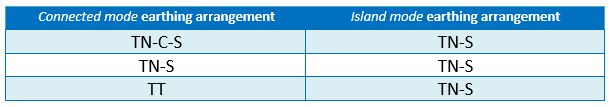
Figure 3 is a simplified illustration of earthing and switch-over arrangements for connected and island mode. It shows the state of island mode isolator and N-E bond relay.
Figure 3: Simplified illustration of earthing and switch-over arrangements in connected mode and island mode
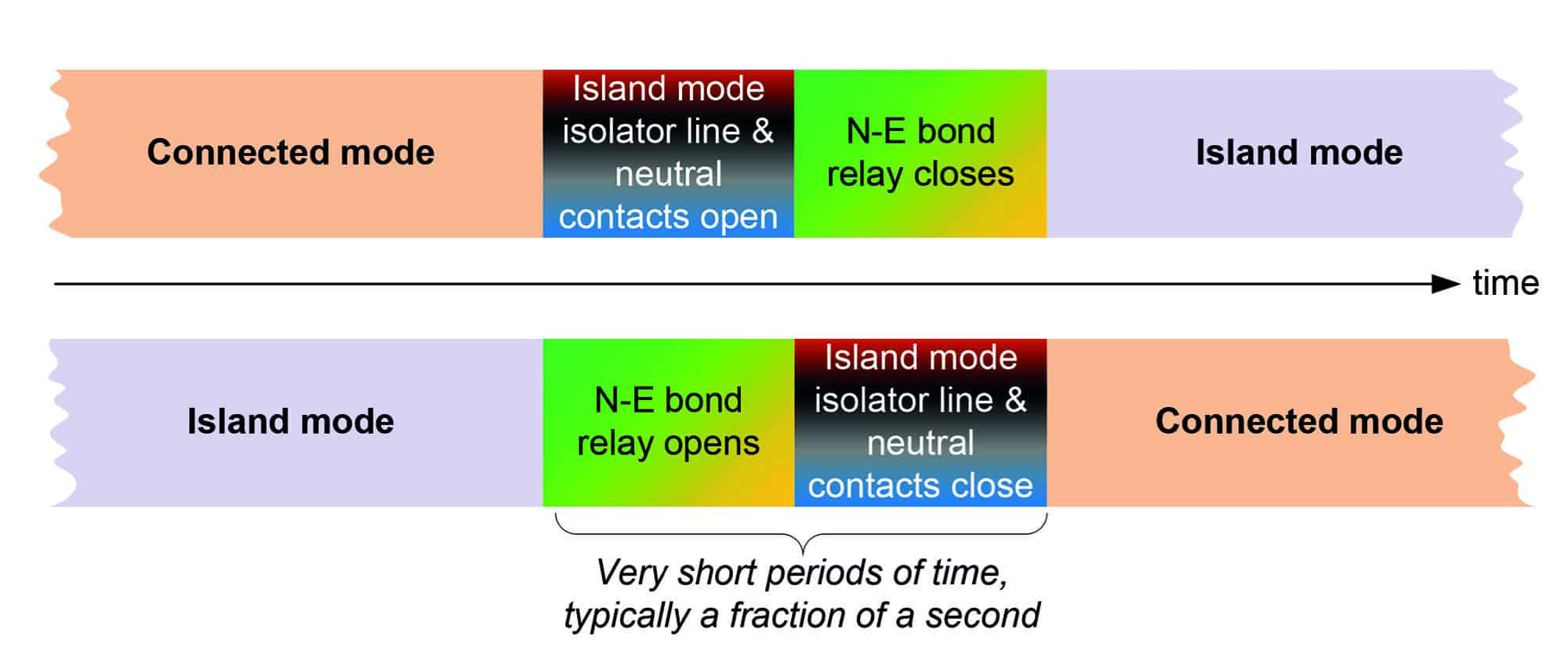
Timing of the operation of the island mode isolator and N-E bond relay should comply with Regulations 431.3 and 537.1.5 of BS 7671. This requires:
- The N-E bond relay to be interlocked, or mechanically linked, with the island mode isolator, as illustrated in Figure 4, so that:
- When moving to island mode, the N-E bond contact is closed immediately after the live conductor contacts of the island mode isolator are opened
- When moving to connected mode, the N-E bond contact should be opened immediately before the live conductor contacts of the island mode isolator are closed
- In polyphase systems, the neutral contact of the island mode isolator should not disconnect before those of the line conductors, and should not reconnect after those of the line conductors.
Figure 4: Timing requirements for island mode switching arrangements
The consumer earth electrode
A consumer earth electrode is required for island mode operation, because, as Regulation 551.4.3.2.1 of BS 7671 states, the distributor’s earthing arrangement cannot be relied upon.
Existing consumer earth electrodes, such as those used in TT systems, may be used where they meet the design requirements for the EESS. The selected earth electrode system should meet the requirements of BS 7671, and as much as possible should be installed to reduce the risk of freezing or drying out.
The maximum acceptable earth electrode resistance for installations operating TN-S, or in TT systems where earth fault loop impedance is not restricted to a lower value, is 200 Ω. Above this value, the earth electrode system may not present a stable resistance. This is a major change in the 2nd Edition of the IET Code of Practice for Electrical Energy Storage Systems, which previously recommended a maximum of 200 Ω only for systems below 10 kVA.
In some cases, better earthing needs to be provided. Some consumers have parts of the installation with different earthing arrangements to the main installation. Examples include installations with a PME earthing arrangement for the grid connection, but separate TT earthing arrangements for outbuildings, or electric vehicle charging equipment. An example is shown in Figure 5.
In these systems, the designer should ensure the values of both the consumer earth electrode for the island mode earthing arrangement, and the TT earth electrodes, are low enough to ensure operation of protective devices in the event of a fault to earth in the TT part of the installation. Usually, this will involve the operation of RCDs, and the maximum earth fault loop impedance must meet Table 41.5 of BS 7671.
Figure 5: Example of an installation where circuits with separate earthing arrangements remain connected in island mode
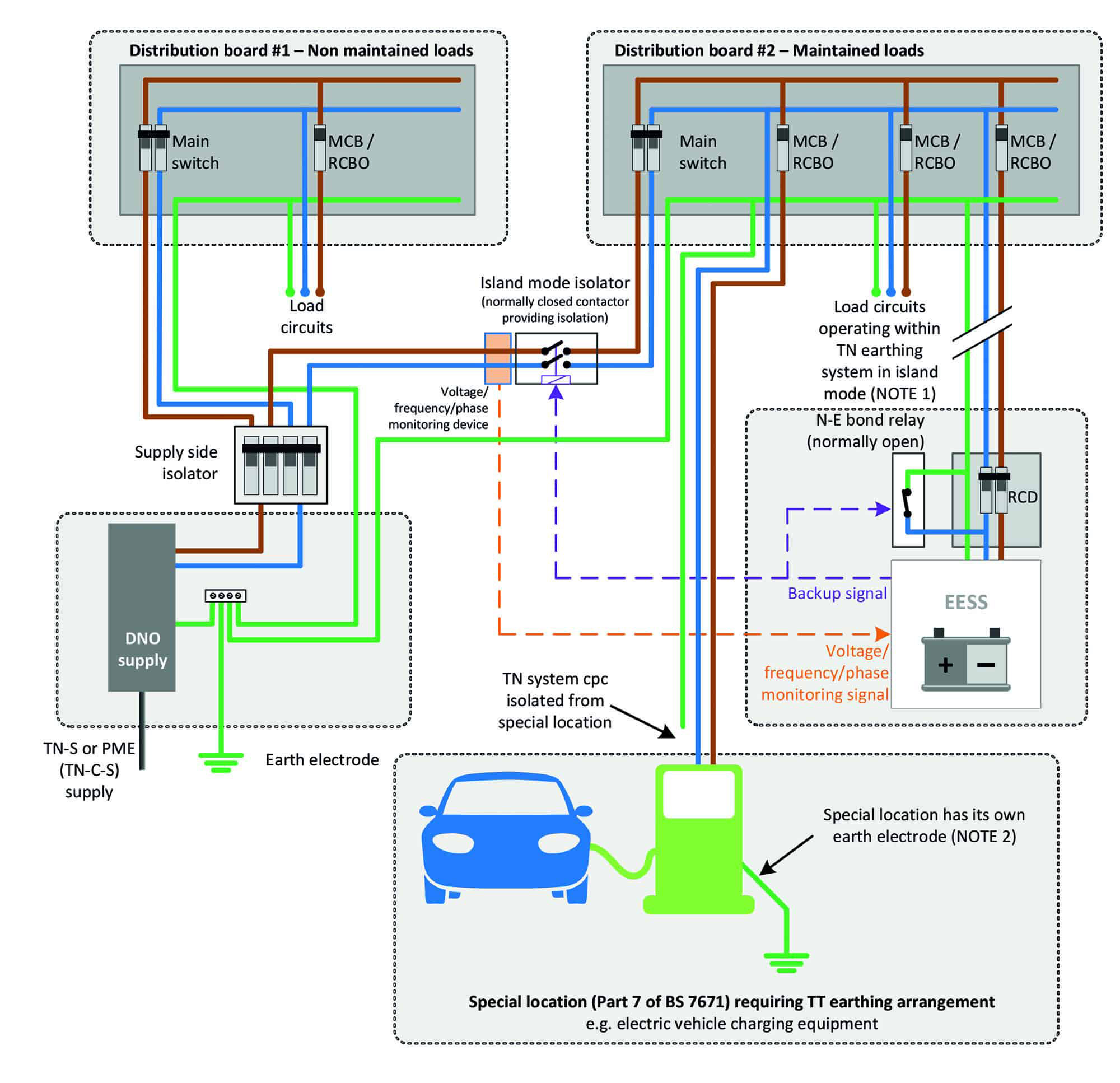
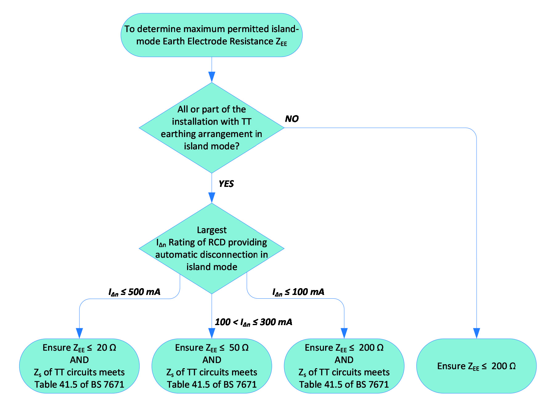
Figure 9.10 of the IET Code of Practice for Electrical Energy Storage Systems. Contains a flowchart to quickly enable the designer to determine the maximum island mode earth electrode resistance. See Figure 6.
Figure 6: Flowchart to determine maximum permitted island mode earth electrode resistance
Protection against electric shock in island mode
Ultimately, the earthing arrangement is essential to facilitate automatic disconnection of supply (ADS). Often, the prospective fault current available from PCE in an EESS will be far lower than that from the grid, and may be insufficient to operate overcurrent protective devices within the times stated in Chapter 41.
To facilitate selectivity in island mode, RCDs can be used to achieve ADS. Section 9 of the IET Code of Practice for Electrical Energy Storage Systems provides comprehensive guidance on means of earthing and protection against electric shock in island mode, as well as guidance on protection against overcurrent in connected mode.
References
- IET Code of Practice for Electrical Energy Storage Systems, 2nd edition (ISBN-13: 978-1-83953-041-8)
- BS HD 60364-8-2:2011+A11:2019 Low-voltage electrical installations. Part 8-2. Prosumer's low-voltage electrical installations
- The Electricity Safety, Quality and Continuity Regulations 2002 (as amended)
- ENA Engineering Recommendation G98 Issue 1 Amendment 4 (June 2019) Requirements for the connection of Fully Type Tested Micro-generators (up to and including 16 A per phase) in parallel with public Low Voltage Distribution Networks on or after 27 April 2019
- ENA Engineering Recommendation G99 Issue 1 Amendment 6 (9 March 2020) Requirements for the connection of equipment in parallel with public distribution networks on or after 27 April 2019
- BS 7671:2018+A1:2020 Requirements for electrical installations. IET Wiring Regulations 18th Edition.
Biographies

Graham Kenyon
Managing Director of the consultancy G Kenyon Technology Ltd, Graham is an electrical and systems engineering consultant who established his reputation designing and implementing control and information management systems in the challenging environments presented by world-class construction programmes, chiefly in the airport and rail sectors.
His experience encompasses project management, systems and product assurance, electrical and systems engineering, and control room design.
He is currently Chair of the IET Wiring Regulations Policy Committee, and Chair of JPEL/64 Sub-Committee D, Special Locations and External Influences for BS 7671.
Graham has authored a number of IET publications and is co-author of the Code of Practice for Electrical Energy Storage Systems, now in its 2nd Edition.

Andrew Crossland
Andrew has a PhD in interdisciplinary modelling of energy systems.
He has worked in the railway, electrical distribution, research, solar and energy storage industries developing new techniques and models for the rapidly changing, and increasingly low carbon energy mix.
He won the Energy UK “Rising Star” Award for his work in the sector in 2017 and was nominated for an Energy Leader award by Energy UK in 2020.
Andrew founded the energy tracking system MyGridGB.co.uk, charting the British electricity mix, carbon emissions and fossil fuel consumption in real-time. Through this, he works to provide an unbiased view of the potential and contribution of different energy sources.
As an Energy Storage Specialist for three years at SolarCentury, Andrew helped to develop residential, large battery and microgrid projects in the UK and Africa. Andrew was also Chair of the Behind the Meter Energy Storage Group at the Solar Trade Association at this time.
In 2018, Andrew joined Infratec working on energy projects across New Zealand and the Pacific where he develops and consults on solar/storage. He is also a director of Advance Further Energy Ltd which provides specialist energy storage consultancy services in the UK.