
The history of colour identification of conductors
Table 1: Colour identification history
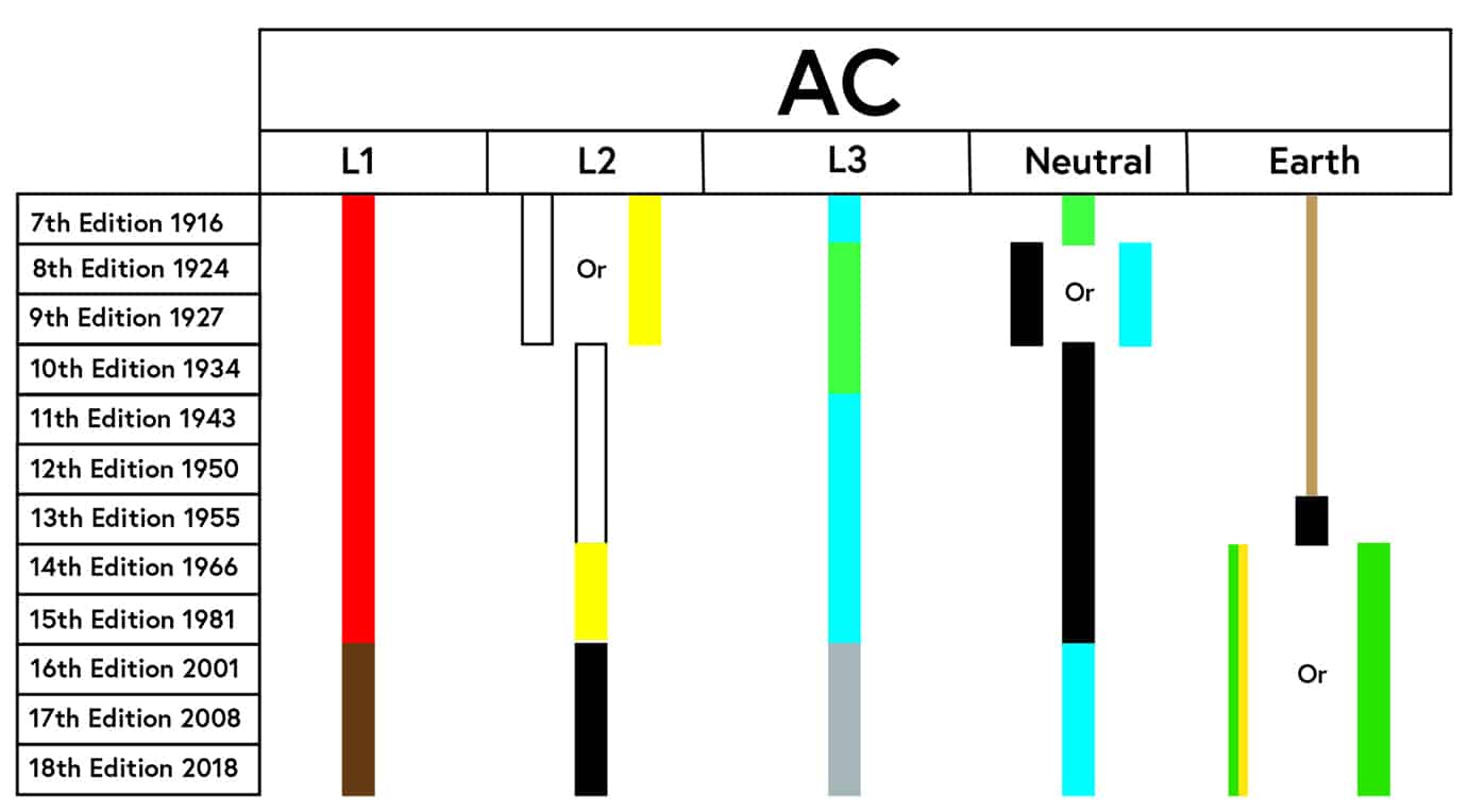
This article looks at the changes over the years, and for simplicity looks at the requirements for AC conductors only. Note that DC was previously referred to as ‘continuous current’, as shown in Figure 1.
Figure 1: Regulation 51 from IEE Wiring Rules 7th Edition 1916
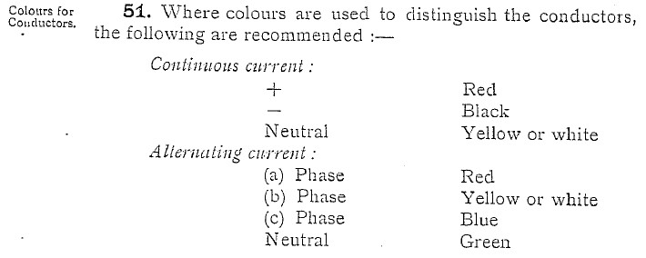
Colour identification of conductors was first introduced in 1916 in the 7th Edition of the IEE Wiring Rules and Regulation 51 made recommendations for identifying conductors by colour, as identified in Figure 1.
Back then, the phases were referred to by the letters (a), (b), and (c), and the colours recommended were red, white (or yellow) and blue respectively. It may be a surprise for some to see that green was used to identify the neutral conductor.
The 8th Edition of the IEE Wiring Regulations was entitled ‘Regulations for the Electrical Equipment of Buildings’ and was issued in 1924. The ‘recommendation’ for identifying cables by colour became a requirement, Regulation 85 stated ‘where colours are used to distinguish the conductors the following shall be employed’. A note stated that the colours adopted for switchboard connections were different from those specified in Regulation 85 for cables and Regulation 63 N referred to British Standard Specification No. 158, which is ‘Marking and arrangement of switchgear busbars, main connections and small wiring’.
Can you imagine how controversial the arguably major changes implemented in the 8th Edition would have been?
Only eight years after the recommendation to identify cables by colour was introduced it became a requirement, but the use of green for neutral is swapped with the L3 phase conductor and blue is used to identify the neutral (it is also worth nothing that black was also an option to identify the neutral conductor).
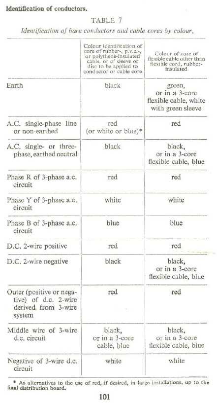
Figure 2: Table 7 from Regulations for the Electrical Equipment of Buildings 13th Edition 1955
The 10th Edition of the IEE Wiring Regulations in 1934 saw the removal of yellow or white as options, with white being the preferred choice for L2. The choice of blue for neutral was also removed. The phase conductors were identified by red, white and green respectively, with black used for the neutral conductor.
The option to use green was removed for a phase conductor in the 11th Edition of the IEE Wiring Regulations in 1943. With the phase colours changing to red, yellow, and blue for phases with black used to identify the neutral.
The 13th Edition of the IEE Wiring Regulations published in 1955, saw the first use of a table for colour identification. ‘Table 7, Identification of bare conductors and cable cores by colour’ specified the requirements for AC and DC conductors is shown in Figure 2. Funnily enough, the phases are referred to as phase R, Y and B for the first time, but the colours specified were red, white, and blue respectively. Also, the colour for earth was specified for the first time, black was used for fixed wiring although green was used in flexible cords.
The 14th Edition of the IEE Wiring Regulations was published in 1966, (not just a good year for football) some would argue that this edition was ‘correct’ in terms of colours. These were the days of using good old red, yellow, and blue for phases with black used to identify the neutral conductor.
The Electrical Appliances (Colour Code) Regulations 1969 came into effect on 1 July 1969 and set the scene. Regulation 4 provided the requirements for the colours for ‘mains leads’ for appliances, brown for live, blue for neutral and green and yellow for earth. Note the requirements for the colour of the ‘earth-continuity conductor’, ‘The covering of the earth-continuity conductor’ shall be coloured green and yellow, and in such a way that the covering (on any length of the conductor measuring 15 mm or more) has not more than 70 per cent. (nor less than 30 per cent.) of its surface coloured one of those colours, and has the remainder of its surface coloured the other.’
Figure 3: Table B.4 from 14th Edition of IEE Wiring Regulation (1966 incorporating Amendments 1970)
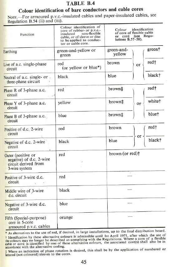
The first use of a bi-colour combination was introduced in the 14th Edition of the IEE Wiring Regulations. There was an option to use green and yellow or green to identify ‘Earthing’ conductors. Note the use of the typographical dagger symbol to signify a note, this symbol was used where the ‘*’ had already been used and it stated that use of these colours were admissible until 1 April 1971.
The use of brown, blue and green/yellow in flexible cables was to align with international standards to facilitate trade. It’s important to remember that in those days, appliances in the UK were sold without a plug attached, so standardized colours for flexible cables would have been a very good idea.
The 15th Edition in 1981 saw the title change to ‘Regulations for Electrical Installations’. The use of green for protective conductors was not included in the 15th Edition, with green and yellow being the only option. In addition to Table 52A, Regulation 524-1 stated that the colour combination of green and yellow was reserved exclusively for identification of protective conductors.
The 15th Edition required one of the colours in the combination to cover at least 30 % and at most 70 % of the surface being coloured, while the other colour covers the remainder of the surface. In reality, the split of colours is much more likely to be 50/50, this is to prevent rejects in product sampling from being too near the limits. The objective, from a manufacturing point of view, is to ensure both colours are visible when looking at the conductor from any angle.
It is more common to see conductors coloured completely yellow with a green stripe on the surface as identified in Figure 4. This is due to the cost of producing the masterbatch colour, which is a factor when determining the ratio of yellow and green with yellow being more cost effective to produce.
Figure 4: Solid yellow coloured insulation with green stripe

Amendment 2 to the 16th Edition of the IEE Wiring Regulations was published in 2004, and introduced some major changes with regards to identification of conductors. The IET Wiring Matters article, harmonised colours and alphanumeric marking, from Spring 2004 looks at the impact of BS 7671.
The process of international alignment was a long process and it took many hours of discussions to reach agreements for the colours we have today. The story of “the blue neutral” goes as far back as 1973, and who better to tell the story than David Latimer, Chair from 1990 to 2002 of IEC TC 64 International Committee and CENELEC TC 64 European committee for Wiring Regulations.
The use of blue as a neutral was originally adopted from IEC 446 published in 1973, what is now IEC 60446 Basic and safety principles for the man-machine interface, marking and identification, which specified blue shall be used for the neutral with black numerically identified phase conductors. At the time of developing this Standard, the Wiring Regulations Committee were not consulted, possibly because it was a BSI committee which was considering the international proposals and they therefore felt that they had no need to consider the Wiring Regulations which were, at that time, not a standard. It is also possible that the BSI committee thought that it applied only to machine wiring.
At that time the Wiring Regulations Committee and IEE representatives on BSI committees both reported to the Public Affairs Board but there was no liaison between them.
In the light of events it is quite clear that, led by Germany, the continental countries had got together and decided that IEC 446 applied to installations, with, in addition, the appliance manufacturers asking for standardization of flex colours to make things easier for them. So it was that, in Berlin in 1974, the UK were told without warning that flexes were to have a blue neutral and the phase conductor would be blue or brown and which did we want? We clearly could not accept black as a phase conductor (Ireland already used blue and black flexes but used black as the neutral and blue as the phase conductor); I went to an ad-hoc working group to discuss the matter, in French, and there was, of course, no alternative to accepting blue for the neutral and so I opted for brown, on condition that the colours of the fixed installation wiring should also be harmonized and they accepted that.
I went back to the Technical Sub-committee and reported what I had done and told them that we needed to harmonize the phase colours and that the other countries were prepared to accept, within reason, what we proposed and that the only available colours were brown, black and white.
There are 11 colours available, red was used as a protective conductor in Germany and Austria, yellow was used as a protective conductor in Italy and green was used in the UK. Orange is not available because it is either too near yellow or too near red, purple is not available because it is too near red or blue and turquoise is not available because it is too near blue. Pink is not available because it is too near red.
That leaves black, brown, grey, and white.
The technical committee, under the influence of David Bryce and later others, did not have harmonization of cable colours on the agenda until I became the chairman of CENELEC TC 64. In the mid-1990s I prepared a chart which showed all the changes which other European countries had made to their colour coding, all adopting blue as the neutral and most black, brown and white. The chart also showed that the UK uniquely had not made any changes. This galvanized JPEL 64 into discussing the matter and over something like 15 years they argued about it and eventually came up with, guess what, brown, black and white. The cable makers then asked for it to be grey rather than white because it was easier to manufacture and this was put to CENELEC TC 64 (I had by then finished my time as chairman) and it was accepted.
David Latimer
I would like to extend my sincerest thanks and appreciation to David Latimer, for the extraordinary insight behind the discussions of ‘the blue neutral’, and his contribution to producing this article, not to mention the opportunity of working with him.