How voltage drop can affect EV charging point open PEN detection devices

Why is an EVCP different to any other final circuit?
When EVCPs first arrived on the scene, they were nothing more than a socket-outlet. As technology has developed rapidly, EVCPs are now sophisticated equipment requiring connection to the internet and compliance with The Electric Vehicles (Smart Charge Points) Regulations 2021.
Not only has the technology become smarter, the requirements for safety have also evolved and the installation of OPDDs has become more common. The installation of an OPDD is often more desirable than installing earth electrodes. It is important that the designer of a final circuit for an EVCP, which features an OPDD, is aware of how they operate.
What is an OPDD?
An OPDD is a device intended to disconnect the live and protective conductors to the EVCP in the event of a broken PEN conductor on the public distribution network. The reason for disconnecting the protective conductor is that in the event of a broken PEN conductor on the public distribution network, the metallic body of the vehicle could become live.
OPDDs are available as a standalone device or can be incorporated in the EVCP. This article focuses on OPDDs which are built into EVCPs. Standalone devices are intended to be installed at the origin of the installation and measure the supply voltage, therefore it is not affected by voltage drop within the installation.
The standalone devices may utilize different voltage parameters to those provided in indent (iv) of Regulation 722.411.4.1 of BS 7671:2018+A2:2022. The manufacturer of the OPDD is best placed to provide information on the voltage operating parameters of their equipment.
Many of the popular EVCPs incorporate some form of protection against open PEN faults. Regulation 722.411.4.1 of BS 7671:2018+A2:2022 provides several methods of operation for open PEN fault protection devices.
The method of protection used for the EVCP is different depending on the manufacturer. Some manufacturers use a combination of several different methods to provide protection. This is covered in indent (v) of Regulation 722.411.4.1 of BS 7671:2018+A2:2022.
How does an OPDD operate?
One of the most popular methods of protection is provided by a device which monitors the utilization voltage at the EVCP. See indent (iv) of Regulation 722.411.4.1 of BS 7671:2018+A2:2022.
The utilization voltage is the voltage at the EVCP and not the supply voltage at the intake position. If the voltage is outside of the parameters stated (207 V – 253 V), the device must disconnect all live conductors and the protective conductor from the supply within 5 seconds.
What is the nominal supply voltage in the UK?
The supply voltage in the UK is 230 V (+10 %/-6 %). That means that the voltage could be as high as 253 V and more importantly, when it comes to voltage drop, the voltage could be as low as 216.2 V. This is set out in Regulation 27 of The Electricity Safety, Quality and Continuity Regulations 2002 (ESQCR).
The supply voltage will vary according to several factors such as cable length, transformer capacity, and also the demand on the network will be a major influence.
When the load on the network is high, the voltage will be reduced and could, in some cases, be as low as 216.2 V but would still be within ESQCR parameters. The electrical designer must take account of this and consider the utilization voltage at the EVCP.
What is the maximum permitted voltage drop in BS 7671?
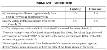
The requirements for voltage drop are that the product standard is consulted, Regulation 525.1 of BS 7671:2018+A2:2022 refers. There are recommended maximum values of voltage drop provided in Table 4Ab in Appendix 4, Section 6.4 of BS 7671:2018+A2:2022. These values are informative because the actual values of voltage drop depend on the requirements of the connected equipment.
For low-voltage installations supplied directly from a public low-voltage distribution system, the recommended maximum voltage drop between the origin and any load point for a load other than lighting, is 5 %.
However, where a maximum voltage drop of 5 % has been factored into the design for a final circuit for an EVCP featuring open PEN protection, unwanted tripping of the device may be experienced.
For installations supplied from a private transformer, it is permissible to allow 8 % (18.4 V) voltage drop. This means that if the nominal voltage at the source is 225 V, the utilization voltage at the EVCP would be 207 V and would cause unwanted tripping of an OPDD.
Figure 1 – Table 4Ab - Voltage drop from Appendix 4, Section 6.4 of BS 7671:2018+A2:2022
What is the maximum permitted voltage drop for an EVCP?
Where an EVCP features a built-in OPDD, it is important to ensure the utilization voltage at the EVCP is not less than the tripping threshold of the OPDD, due to voltage drop of the cable to the EVCP.
If 5% voltage drop is applied to an EVCP, the user may experience unwanted tripping of the device. If the supply voltage at the installation is 216.2 V, taking into account a 5 % (11.5 V) voltage drop would mean the utilization voltage at the EVCP would be 204.7 V and trip the OPDD.
For an allowance of 4 % (9.2 V) voltage drop, the same problem exists because the utilization voltage at the EVCP would be 207 V, which is the lower trip threshold for an OPDD.
However, if 3 % (6.9 V) voltage drop is applied, the utilization voltage at the EVCP is 209.3 V exceeding the lower trip threshold of an OPDD as shown in Table 1 below.
Table 1 – Voltage drop calculations
|
Supply voltage + 10% |
253 V |
||
|
Supply voltage |
230 V |
||
|
Supply voltage -6 % |
216.2 V |
||
|
Voltage drop (%) |
3 % |
4 % |
5 % |
|
Voltage drop (V) |
6.9 V |
9.2 V |
11.5 V |
|
Supply voltage (–6 %) – voltage drop = utilization voltage |
216.2 V - 6.9 V = 209.3 V |
216.2 V - 9.2 V = 207 V |
216.2 V - 11.5 V = 204.7 V |
|
Lower trip threshold for open PEN device |
207 V |
||
What is the most appropriate table to use for XLPE cables?
The cable of choice for the installation of EVCPs would usually be steel wired armoured (SWA) due to requirements for mechanical protection. A common mistake is to think that Table 4E4A and 4E4B should be used for thermosetting (XLPE) SWA cables.
However, this table is for XLPE cables rated at 90 °C, and this temperature is not permitted at switchgear and accessories. Regulation 512.1.5 of BS 7671:2018+A2:2022 provides requirements regarding compatibility of equipment which limits the operating temperature to 70 °C.
It would probably be more appropriate to use Table 4D4A and 4D4B of BS 7671:2018+A2:2022 for thermoplastic cables as the conductor temperature is limited to 70 °C.
What is the maximum circuit length for an EVCP?
Taking the 3 % voltage drop into account, based on a 7 kW EVCP with a current rating of 32 A, according to Table 4D4B with an allowance of 3 % for voltage drop, the maximum circuit lengths are listed in Table 2 below and calculated based on the formula below.
Voltage drop=(mV/A/m) x Ib x Length/1000
Table 2 – Maximum cable length with an allowance of 3 % voltage drop
|
Voltage drop calculation Table 4D4B – single-phase two-core (column 2) |
||||
|
CSA (mm²) |
Length (m) |
Ib |
mV/A/m |
3 % VD |
|
4 |
19 |
32 |
11 |
6.7 |
|
6 |
29 |
32 |
7.3 |
6.8 |
|
10 |
49 |
32 |
4.4 |
6.9 |
|
16 |
77 |
32 |
2.8 |
6.9 |
Other design considerations
To overcome voltage drop issues, the designer may choose to select a larger CSA conductor. However, it is important to take account of the maximum conductor size for the terminals in the equipment.
Energy losses are an important factor when selecting the appropriate conductor size. A smaller conductor will mean more energy losses, and this can be significant when considering high power loads used over long periods of time.
Summary
EVCPs that incorporate an OPDD require additional consideration with respect to voltage drop. It is important to consider the lower trip threshold of the OPDD.
Applying the maximum recommended voltage drop of 5 % for a final circuit to an EVCP circuit featuring open PEN protection might frustratingly result in unwanted tripping of the device.
Standalone OPDDs are not affected by voltage drop within the consumers installation. Manufacturers of OPDDs are best placed to provide guidance on voltage parameters for their equipment.
Further reading
The IET has developed a standard for OPDDs for use in electric vehicle charging applications. There will be an opportunity to comment on the DPC later this year. The details will be announced on the IET website shortly.
For further information on PEN conductor faults, see the IET Wiring Matters Broken PEN article.
Further information on temperature ratings of cables can be found in the IET Wiring Maters article Thermoplastic (SWA) or Thermosetting (XLPE) SWA cable article.
Acknowledgments
I would like to extend sincere thanks to the following individuals for their valuable contributions and continued support:
- Gary Gundry
- Graham Kenyon
- Joe Cannon
- Leon Markwell
- Mark Coles