
Derating grouped circuit-breakers within a consumer unit due to mutual thermal influences
1. What are the requirements for derating grouped circuit-breakers within a consumer unit?
Circuit-breakers serving continuous loads from a consumer unit may require derating when grouped together. This is due to the thermal interaction between the circuit-breakers when serving continuous loads. In a similar manner to derating cables installed in a group, designers should apply derating factors to grouped circuit-breakers when continuously loaded.
It is the consumer unit manufacturers who will specify the derating factor, which is referred to as the rated diversity factor (RDF). The rated diversity factor is generally applied to thermal-magnetic circuit-breakers that are continuously loaded and that are placed adjacent to other circuit-breakers that are also continuously loaded. The rated diversity factor is applied to ensure that the heat emitted from the circuit-breaker stays within a tolerable value when under continuous load.
As the demand increases for electrical equipment that has a sustained load, such as electric vehicle charging points and heat pumps, it is crucial for designers to recognize the thermal impact these circuits can have. It is important to determine and apply the appropriate rated diversity factor to circuit-breakers in order to accommodate these loads effectively.
This article explores the concept of the rated diversity factor, highlighting its significance for designers, and provides guidance on its application to circuit-breakers within a consumer unit.
2. What is the rated diversity factor?
The rated diversity factor is defined in BS EN 61439-1:2011 as:
Per unit value of the rated current, assigned by the assembly manufacturer, to which outgoing circuits of an assembly can be continuously and simultaneously loaded taking into account the mutual thermal influences.
The per unit value of the rated current can be more easily understood as a percentage value of the rated current. For instance, 1 represents 100 %, 0.5 represents 50 %, and so on. As an example, a per unit value of 0.5 applied to a rated current of 32 A would correspond to 16 A (32 A x 0.5 = 16 A).
Note: Multiplying the rated diversity factor by 100 will give the percentage value.
This article covers rated diversity factors in relation to outgoing circuits of consumer units, which are included in BS EN 61439-3:2012 and are referred to as ‘Distribution boards intended to be operated by ordinary persons...’. ‘Consumer unit’ is a UK term used to describe this type of assembly.
Consumer unit is defined in BS 7671:2018+A2:2022 as follows:
Consumer unit (may also be known as a consumer control unit or electricity control unit)
A particular type of distribution board intended for operation by ordinary persons, comprising a type-tested coordinated assembly for the control and distribution of electrical energy, incorporating manual means of double-pole isolation on the incoming circuits(s) and an assembly of one or more protective devices, signalling and other devices proven during the type-test of the assembly as suitable for such use.
The rated diversity factor is assigned by the manufacturer of the consumer unit, which is then used by the designer when determining the size of the protective device. The manufacturer can assign the rated diversity factor to a consumer unit as a whole or may choose to specify it in relation to a group of circuits within the consumer unit.
Complete assembly rating
When a whole assembly rating is assigned by a manufacturer, this is the manufacturer specifying the average permissible loading conditions of the outgoing circuits.
Grouped circuit rating
When the rated diversity factor relates to a group of circuits, it is generally only applicable when the load of the circuit is continuous and has adjacent simultaneously loaded circuits.

3. What determines if a load is continuous or intermittent?
Rated diversity factors are generally only applicable to continuously and simultaneously loaded circuits. A continuous load is not defined in the BS EN 61439 series, although examples of what may be interpreted as continuous loads and what may be interpreted as intermittent loads are given below.
Continuous load
Continuous loads are not explicitly defined in the BS EN 61439 series, although the standard highlights the importance of being cautious with loads that remain energized for durations exceeding 30 minutes. Manufacturers' information varies, with some specifying a continuous rating for loads active for more than 30 minutes, while others indicate on-times exceeding 1 hour.
A circuit supplying a load with longer on-times than off-times may also be treated as a continuous load, as there may not be sufficient cooling time between on-periods. However, this is typically relevant only when the load current approaches the circuit-breaker's rating. An example of a continuous load is an electric vehicle charging point, where the continuous current may be sustained for several hours.
In summary, although the exact definition may vary, it is important to consider loads with extended on-times and their impact on thermal performance.
Intermittent load
Intermittent loads can be characterized as loads that are inactive for longer periods than they are active, typically with on-times shorter than 30 minutes. Kitchen appliances, such as washing machines operating in varying load cycles, and thermostatically controlled cooking equipment are examples of intermittent loads. These appliances go through cycles of operation where their on-time and load fluctuate, resulting in intermittent energy consumption patterns.
A calculation can be carried out to determine the root mean square (RMS) (average) current for an intermittent circuit, which can then be used to determine the rated diversity factor, although this is out of the scope of this article. For further reading see Annex E of BS EN 61439-1:2011.
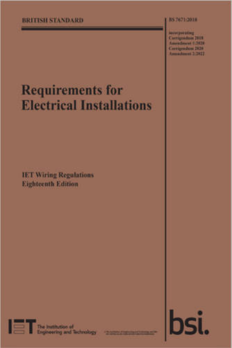
Figure 1 – IET Wiring Regulations, 18th Edition
4. Rated diversity factor and BS 7671 requirements
Within Part 5 of BS 7671:2018+A2:2022, it states the following regarding the current ratings of an assembly:
536.4.202 Current ratings
The relevant design current shall not exceed the rated current of an assembly (InA) or rated current of a circuit (Inc) of the associated assembly, having taken any applicable diversity/loading factors into account.
The terminology used to define the rating of an assembly concerning load/design current used in the BS EN 61439 series can be summarized as follows:
- The rated current of an assembly (InA) (A) is the maximum load current that it is designed to manage and distribute.
- The rated current of a circuit (Inc) (A) is stated by the manufacturer, taking into consideration the rating of the devices within the circuits, their disposition and application.
The current rating(s) of an assembly circuit may be lower than the rated current(s) of the device(s) according to their respective device standard when installed in the assembly; therefore, the assembly manufacturer’s ratings and instructions shall be taken into account.
For compliance with BS 7671:2018+A2:2022, the designer shall consider the rated diversity factor when designing the installation’s circuits.
5. Why have a rated diversity factor?
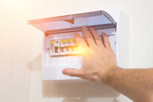
Consumer unit manufacturers perform temperature rise verification as per the requirements outlined in BS EN 61439-3:2012. This verification ensures that the consumer unit remains within acceptable temperature limits and does not overheat during operation. The circuits in an assembly, when continuously loaded and placed adjacent to circuits that are simultaneously continuously loaded, have a mutual thermal influence.
Generally, it wouldn’t be economical for a manufacturer to rate the full assembly with all outgoing circuits rated at 100 %, as this isn’t how circuits connected to consumer units are generally loaded. To address this, BS 61439-3:2012 provides guidance for manufacturers, which recognizes that circuits in practice are not continuously and simultaneously loaded. Specifying a rated diversity factor enables manufacturers to economically design a consumer unit.
The rated diversity factor enables manufacturers to design consumer units that account for the practical loading conditions of circuits, ensuring efficient and safe operation while maintaining cost-effectiveness.
6. Where to find the rated diversity factor of a consumer unit
Manufacturers of consumer units may apply a rated diversity factor derived from testing or may use the table below from BS EN 61439-3:2012, which states the assumed loading factor and is based on the number of outgoing circuits of the consumer unit. The assumed loading factor is the maximum permitted rated diversity factor to be applied by the user.
BS EN 61439-1:2011 states: “The rated diversity factor multiplied by the rated current of the circuits shall be equal to or higher than the assumed loading of the outgoing circuits”.
Table 1 - Based on assumed loading factors from BS EN 61439-3:2012 (Table 101)
|
Number of outgoing circuits |
Assumed loading factor |
|
2 and 3 |
0.8 |
|
4 and 5 |
0.7 |
|
6 to 9 inclusive |
0.6 |
|
10 and above |
0.5 |
It is the responsibility of the manufacturer of the consumer unit to agree with the user (designer) on the required rated diversity factor of their equipment. Installation instructions may take the place of an agreement.
A selection of consumer unit installation instructions were downloaded from various websites. A summary of the assigned rated diversity factors is reported below. Where text accompanied the ratings, it has been included.
For accurate and up-to-date information, please refer to the instructions provided with a consumer unit.
British General Fortress
Table 101 from BS EN 61439-3:2012 is used.
BG Note: RDF only applies to continuously and simultaneously loading circuits. In principle, this means adjacent circuit-breakers having a load ‘on’ time exceeding 30 minutes, or where a load not exceeding 30 minutes has an ‘off’ time less than the ‘on’ time, will need to have the rating diversity factor applied as indicated. Table and ratings based on a continuous rating of 90A.
Contactum defender
Table 101 from BS EN 61439-3:2012 is used.
Fusebox F2 series
Adjacent thermal-magnetic MCBs should not be continuously loaded at their nominal rated currents when mounted in enclosures. We recommend a 60% derating factor is applied to the MCBs nominal rated current where it is intended to load the MCBs continuously.
Hager Design 30
Table 101 from BS EN 61439-3:2012 is used.
Note: RDF only applies to continuously and simultaneously loaded circuits.
In principle, this means adjacent circuit-breakers having a load ‘on’ time exceeding 30 minutes, or where a load not exceeding 30 minutes has an ‘off’ time less than the ‘on’ time, will need to have the rated diversity factor applied as indicated.
Lewden QFS range
Table 101 from BS EN 61439-3:2012 is used.
Adjacent thermal magnetic MCBs/RCBOs should not be continuously loaded at their nominal rated currents when mounted in enclosures. We recommend a diversity factor (RDF) is applied to the MCB/RCBO nominal rated current where it is intended to load circuits continuously and simultaneously.
Live LHMC specification
Adjacent Thermal Magnetic MCBs should not be continuously loaded or approach their nominal rated currents when mounted in enclosures. It is recommended that a 60% diversity factor be applied to the MCBs nominal rated current where it is intended to load the MCB continuously.
MCG Industrial
Adjacent thermal-magnetic MCBs should not be continuously loaded or approaching their nominal rated current when mounted in the enclosure. Therefore, we recommended 60% diversity factor is applied to the MCBs nominal rated current where it is intended to load the MCBs continuously.
Wylex NM range
Adjacent thermal-magnetic MCBs should not be continuously loaded or approaching their nominal rated currents when mounted in enclosures. It is good engineering practice to apply generous derating factors or make provision for adequate free air between devices.
In these situations, and in common with other manufacturers, we recommend a 60% diversity factor is applied to the MCB nominal rated current where it is intended to load the MCBs continuously (in excess of 1 hour).
Note: Rated diversity factor (RDF) only applies to continuously and simultaneously loaded circuits.

7. How the rated diversity factor is used by designers
When establishing the current rating of a circuit-breaker, designers must assess whether the inclusion of the rated diversity factor is necessary. If the designer identifies the presence of outgoing circuits that are continuously and concurrently loaded, they will proceed to determine the specific value of the rated diversity factor. The rated diversity factor is typically found within the manufacturer’s installation instructions.
When the rated diversity factor is applied to the rated current of the circuit (Inc), the value obtained is the grouped circuit rating (Ing). The design current of the circuit (Ib) should be less than or equal to the grouped circuit rating (Ing) (Ib≤Ing).
Ing is defined in BS EN IEC 61439-1:2021[1] as “the rated current which a main circuit can carry considering the mutual thermal influences of the other circuits that are simultaneously loaded in the same section of the assembly”.
Worked example 1
A heat pump with a continuous load current of 32 A is to be served by a consumer unit. The circuit-breaker serving the heat pump will be installed adjacent to circuit-breakers serving intermittent loads.
From the manufacturer’s instructions of the selected consumer unit, a rated diversity factor of 1 is declared for one continuously rated circuit. To determine the current to be used to size the circuit-breaker, the following calculation is carried out:
Current to be used for circuit calculation= Ib/RDF
Current to be used for circuit calculation= 32 A/1
Current to be used for circuit calculation= 32 A
Where:
Ib is the design current for the circuit
and
RDF is the declared rated diversity, or assumed loading factor, as determined by the consumer unit manufacturer.
From the worked example, the circuit-breaker will be rated at a minimum of 32 A. The rated diversity factor did not have an effect on the circuit’s current rating. The cable’s cross-sectional area will be based on a circuit-breaker rating of 32 A.
By following the requirements set out in Regulation 433.1.1 of BS 7671:2018+A2:2022, Ib≤In≤Iz, the cable’s cross-sectional area will be based on a circuit-breaker rating of 32 A.
Worked example 2
A heat pump with a continuous load current of 32 A is to be served by a consumer unit. The circuit-breaker serving the heat pump will be installed with adjacent circuits to the left and right, serving an electric vehicle charging point and a solar PV system respectively.
From the manufacturer’s instructions of the selected consumer unit, a rated diversity factor of 0.6 is declared. To determine the current to be used to size the circuit-breaker, the following calculation is carried out:
Current to be used for circuit calculation= Ib/RDF
Current to be used for circuit calculation= 32 A/0.6
Current to be used for circuit calculation= 53.3 A
Where:
Ib is the design current for the circuit
and
RDF is the declared rated diversity, or assumed loading factor, as determined by the consumer unit manufacturer.
From the worked example, the circuit-breaker will be rated at a minimum of 53.3 A with the next standard size up of circuit-breaker being a 63 A device.
By following the requirements set out in Regulation 433.1.1 of BS 7671:2018+A2:2022, Ib≤In≤Iz, the cable’s cross-sectional area will be based on a circuit-breaker rating of 63 A.
To verify the design from worked example 2, or alternatively to check an existing circuit for compliance, the grouped rating can be determined as follows:
Ing= Inc x RDF
Ing= 63 A x 0.6
Ing= 37.8 A
Where:
Inc can be substituted for the rating of the protective device (In).
The design current of the circuit was 32 A, which is less than the determined grouped circuit rating of 37.8 A, therefore the design is compliant as Ib≤Ing.
The actual rated diversity factor for this circuit can be determined with the following calculation:
RDF= Ib/Inc
RDF= 32 A/63 A
RDF= 0.51
Note: The manufacturer of the heat pump may specify a maximum permissible circuit-breaker rating. This must be considered when designing a circuit and may be rated lower than the device that is determined when applying a rated diversity factor. Another consideration would be to ensure the terminal capacity of the load device is sufficient for the cable’s cross-sectional area that is specified by the designer.
8. Why thermal-magnetic devices?
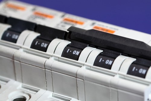
The rated diversity factor is to be assigned to thermal-magnetic devices and not devices such as switch disconnectors and residual current circuit-breakers (RCCBs). The principal workings of the thermal part of a thermal-magnetic device is that the current from the load heats a bi-metallic strip that releases and opens the circuit in the event of an overload.
The heat in the bimetallic strip is proportional to the load of the circuit. In effect, each circuit-breaker is a resistive heater. The greater the number of circuit-breakers that are carrying continuous current, the greater the heating effect within the consumer unit. When a circuit-breaker’s rating is increased in ratio to its load, the lower the heating effect of the protective device.
Note: When the ambient temperature surrounding the circuit-breaker is above the value stated by the manufacturer, the circuit-breaker's sensitivity is increased and will require less current to operate.

9. How to avoid using the rated diversity factor
To avoid the need to apply the rated diversity factor to circuit-breakers, certain measures can be taken to enhance cooling. One approach is to strategically arrange the circuit-breakers to facilitate cooling. This can be accomplished by introducing blanks between circuit-breakers where they are continuously loaded.
If there is sufficient room available in the location of the consumer unit, the consumer unit itself can be oversized, allowing for the installation of a greater number of blanks. Another method involves separating the continuously rated circuits that operate close to their circuit-breaker's capacity and situating them alongside circuits that either have a lighter load* or operate intermittently.
By carefully planning the arrangement of circuits within the consumer unit during the design phase and breaking the conventional practice of grouping circuit-breakers based on their rating, it is possible to improve cooling efficiency. This strategic placement of circuits may eliminate the need for a rated diversity factor.
*Circuits that experience continuous but light loads tend to have a low rated diversity factor. For instance, consider a lighting circuit in a domestic premises that carries a load of 1 A (equivalent to 230 W) and is protected by a 6 A circuit-breaker, resulting in a rated diversity factor of 0.17. Since this circuit is lightly loaded, it is possible to position the circuit-breaker serving this particular circuit adjacent to a circuit with a higher continuous load, eliminating the necessity for applying a rated diversity factor to the larger loaded circuit.
10. Adding a circuit to an existing consumer unit
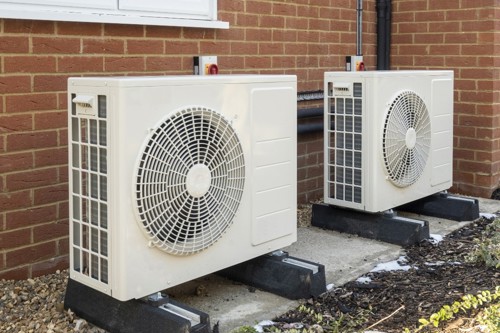
When adding a new circuit, such as a heat pump, into an existing consumer unit that may already serve a continuous load, such as an electric vehicle charging point, the designer must reassess the loading of the consumer unit.
This evaluation is necessary to ensure that any intended additions, which were not initially considered during the design phase, do not adversely affect the thermal performance of the existing consumer unit. By conducting this re-evaluation, the designer can ascertain if the proposed addition will place excessive thermal strain on the consumer unit [2].
Regulation 132.16 from BS 7671:2018+A2:2022 states:
No addition or alteration, temporary or permanent, shall be made to an existing installation, unless it has been ascertained that the rating and the condition of any existing equipment, including that of the distributor, will be adequate for the altered circumstances. Furthermore, the earthing and bonding arrangements, if necessary for the protective measure applied for the safety of the addition or alteration, shall be adequate.
11. Conclusion
As the nature of loads connected to consumer units in domestic electrical systems are changing, the significance of the rated diversity factor is becoming more evident for designers. Traditional domestic loads were often intermittent or lightly loaded, however, designers now face the challenge of incorporating loads, such as electric vehicle charging points and heat pumps, into their designs.
To address the issue of the mutual heating effect of circuit-breakers, electrical designers have the option to position board blanks adjacent to circuits with continuous loads. They may also ensure that circuits that are continuously loaded at a current that is near their circuit-breakers’ rating, are placed apart from each other within the consumer unit.
In either case, designers must consider the rated diversity factor and be mindful of the thermal interaction between circuit-breakers. This consideration is also important when adding a new circuit to an existing consumer unit.
An additional point worth mentioning is the impact of solar photovoltaic (PV) installations on existing consumer units when they are directly connected. With the increasing popularity of solar PV generation, it is important to consider the heat generated within the consumer unit when directly connected to the PV system via a thermal-magnetic circuit-breaker.
Also, take note of 551.7.2 of BS 7671:2018+A2:2022 when connecting solar PV to a consumer unit.
Notes/references:
[1] BS EN IEC 61439-1:2021 supersedes BS EN 61439-1:2011, which is to be withdrawn on 21 May 2024.
[2] BEAMA guide on coordination between design current of an installation and rated currents in panelboards, switchboards and motor control centres (BS EN 61439-2).
Further reading:
- BEAMA guide on coordination between design current of an installation and rated currents in panelboards, switchboards and motor control centres (BS EN 61439-2).
- BEAMA consumer unit checklist -https://www.beama.org.uk/resourceLibrary/beama-publishes-consumer-unit--safety-checklist.html
- IET article on consumer units -https://electrical.theiet.org/courses-resources-career/free-resources/consumer-guidance/consumer-units/
- IET Wiring Matters article on thermal effects -https://electrical.theiet.org/wiring-matters/years/2021/86-july-2021/back-to-the-forum-thermal-effects/
Acknowledgements:
I would like to thank the following for their valuable contribution to this article:
- Leon Markwell
- Susannah Girt
- Gordon Banks
