
Back to the Forum - Thermal effects
Renewable electricity will play a crucial part in achieving ambitious UK Government emission targets, but this will mean an increased maximum demand for electrical installation. In this article, we look at the effects of increased temperature and thermal effects on cables and consumer units.
Heat pump technology
Following a recent Future Homes Standard consultation, the UK Government has published a report stating that heat pumps are anticipated to become the primary heating source for dwellings.
The principle of a heat pump is to utilize energy in the air and convert it into heat using electricity. A typical size dwelling requires an air source heat pump with a heat output of 12 kW, this would have an electrical load of 3 kW, if the coefficient of performance (COP) of the heat pump is 4.0.
The COP is dependent on the external temperature and will reduce in the colder weather, making it less efficient. Below certain external temperatures a backup heater is required which consumes an additional 3 kW.
Electric vehicles
The Road to Zero strategy sets out UK Government targets for zero carbon transport by 2050. Car manufacturers have already brought forward the deadline to stop manufacturing petrol and diesel vehicles from 2035 to 2030.
A typical EV charger for a domestic home is rated at 7 kW, but some fast chargers are rated at 22 kW which would require a three-phase supply.
Increased maximum demand for domestic electrical installations
If you consider the diversified maximum demand for a typical domestic electrical installation with gas central heating is likely to be less than 2 kW. The combined load of 13 kW or 56 A for an EV charger and heat pump is a significant additional load for a consumer unit that the installation designer must not ignore.
Unlike other high demand loads, such as electric showers, which are only used for a short period of time, minutes rather than hours, electrical loads such as EV chargers and heat pumps run for considerably longer periods of time, usually several hours. High loads used for an extended period of time produce significant amounts of heat and this must be considered by the electrical designer. Excessive heat in electrical installations can cause overheating of cable terminations and malfunction of equipment.
As the load is increased, the temperature within the consumer unit will rise. It is important to ensure that the temperature rise limits of the manufacturer are adhered to. We are accustomed to applying derating factors for cables installed in groups, but the same can’t always be said for grouping of protective devices.
Can I use a spare way on a consumer unit?
Whilst it may be tempting to use a spare way on the consumer unit, before doing so it is important to consider the loading of the existing installed circuits and the rated diversity factor of the consumer unit to make sure there is sufficient spare capacity available.
What is rated diversity factor?
Rated diversity factor (RDF) is a correction factor based on temperature rise limits, that are applied to take account of the heat produced within the enclosure. When circuit-breakers within a consumer unit are grouped the RDF must be applied to the number of simultaneous loaded circuits installed, this is called the RDF and is based on temperature rise limits.
Whether designing a new installation or when adding a new circuit to an existing installation, it is important to consider the RDF. Failure to observe it could lead to overheating and therefore become a fire risk.
It’s important to remember that RDF only applies to continuously loaded circuits. This means that adjacent circuit-breakers where the load may exceed 30 minutes or where a load which does not exceed 30 minutes but has an ‘off’ time which is less than the ‘on’ time are required to have an RDF applied. Ultimately the correct RDF to apply is subject to agreement with the manufacturer.
The manufacturer may at their discretion declare a RDF for all outgoing circuits, groups or individual outgoing circuits within an assembly. Manufacturers are best placed to provide guidance on the correct RDF to apply. Failure to observe the RDF could cause overheating issues but it is also likely to affect the operating characteristics of the protective devices.
Ambient temperature correction
Ambient temperatures affect the operating sensitivity of circuit-breakers because the principle of operation for these devices is a bi-metallic strip that is affected by heat.
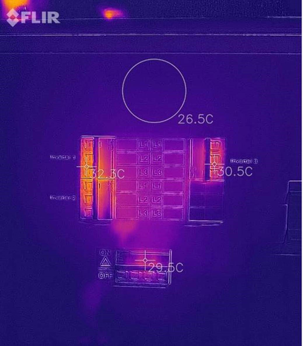
For example, a 40 A circuit-breaker to BS EN 60898 as indicated in Figure 1 is designed to operate when overload current exceeds 44 A at an ambient temperature of 20°C. If the temperature within the enclosure increases to 60°C, the circuit-breaker sensitivity is increased, and it is likely to operate closer to 38 A and could cause unwanted tripping.
Figure 1 is an image of a four-way three-phase distribution board taken with a thermal imaging camera. There are three 40 A, three-phase circuit-breakers installed for PV inverters with a maximum output of 36 A per phase. The image was taken on a cloudy day and the ambient temperature of the location of the distribution board was 23°C. It is evident that the temperature is increased near the protective devices grouped together on the left and it is also increasing the ambient temperature of the enclosure.
Figure 1: an image of a four-way three-phase distribution board taken with a thermal imaging camera
Can I use XLPE cable to achieve higher current carrying capacity?
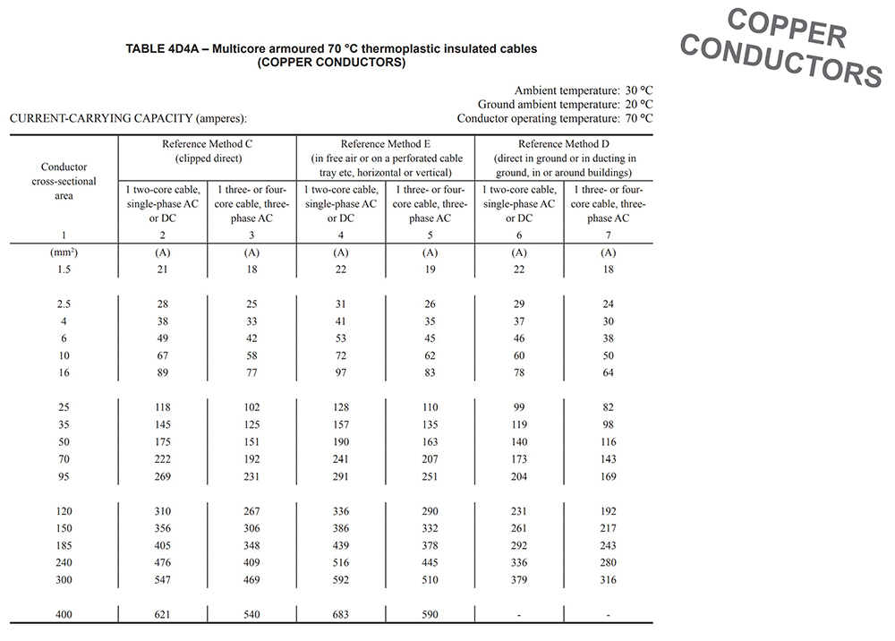
It is often said that cross-linked polyethylene (XLPE) cable can be used to achieve higher current carrying capacity from the same cross-sectional area. However, unless it can be assured by the manufacturer of the switchgear and accessories, which is highly unlikely, conductor temperature must not exceed 70°C. Therefore, the tables 4E1 to 4E4 from Appendix 4 of BS 7671:2018+A1:2020 cannot be used directly and the tables 4D1 to 4D5 for 70°C PVC should be used as shown in Figure 2.
Figure 2: Table 4D4A - multicore armoured 70°C thermoplastic insulated cables
What is the rating of an XLPE cable?
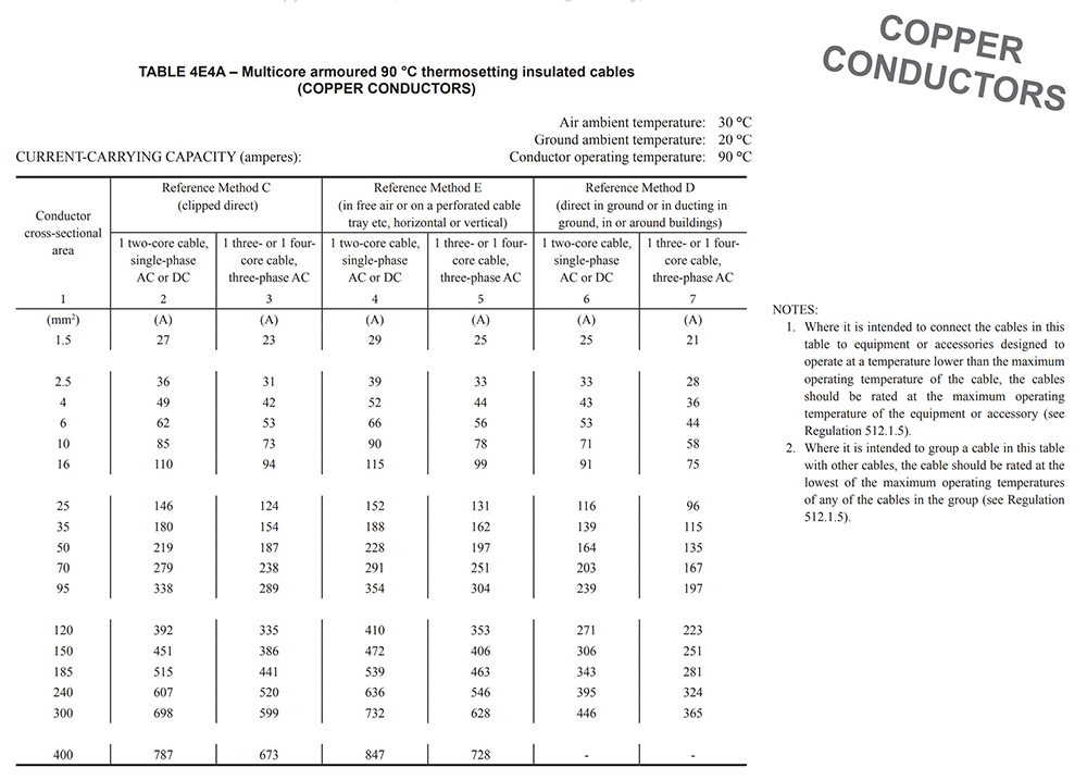
Table 4E4A of BS7671:2018+A1:2020 is indicated in Figure 3, the table is used for XLPE multicore armoured 90 °C thermosetting cables. It is important to read the notes to the right of the table, note 1 states that ‘where it is intended to connect cables in this table to equipment or accessories designed to operate at the maximum operating temperature of the equipment or accessory (see Regulation 512.1.5).’
Note 2 states that ‘where it is intended to group a cable in this table with other cables, the cable should be rated at the lowest of the maximum operating temperatures of any of the cables in the group (see Regulation 512.1.5).’ This can sometimes be overlooked by designers.
Some electrical design software provides an option for 90°C thermosetting cables to be selected but run at 70°C. This allows the designer to select the particular cable, but it uses the values for thermoplastic cables to comply with BS 7671:2018+A1:2020.
Sizing of cables for circuits with long cyclic loads
When considering sizing of cables for circuits with high loads, increasing the conductor size will not only allow the cable to operate at lower temperatures, it will also reduce I2R losses and can provide a payback when considered against the additional capital expenditure for the increased cable size. This payback time will be reduced as the cost of electricity increases.
Figure 3: Table 4E4A - multicore armoured 90°C thermosetting insulated cables
What are the requirements of Regulation 512.1.5 of BS 7671:2018+A1:2020?
Regulation 512.1.5 of BS 7671:2018+A1:2020 sets out the requirements for compatibility. This requirement is to ensure ratings of equipment are not exceeded by cables operating at higher temperatures. It states that ‘every item of equipment shall be selected and erected so that it will neither cause harmful effects to other equipment nor impair the supply during normal service including switching operations.
Switchgear, protective devices, accessories and other types of equipment shall not be connected to conductors intended to operate at a temperature exceeding 70 °C at the equipment in normal service unless the equipment manufacturer has confirmed that the equipment is suitable for such conditions, or the conductor size shall be chosen based on the current ratings for 70°C cables of a similar construction.
Note 4 provides clarity on the correct tables to be used, it states that ‘where the current rating is to be based on 70°C, current-carrying capacities given in Tables 4D1 to 4D5 or 4H1 to 4H4 of Appendix 4 may be used for 90°C thermosetting insulated cables.’
Summary
The maximum demand of electrical installations will undoubtedly increase as heating and transportation energy is switched to electricity.
It is important to check that consumer units, cables and protective devices are adequately rated for the design current considering the load, rated diversity factor and cyclic duty.
Failure to observe RDF is likely to cause unwanted tripping of protective devices, overheating of connections and malfunction of equipment.
The ratings for PVC thermoplastic 70°C cable should be used for XLPE thermosetting 90°C cable unless the appropriate derating factors can be obtained to assure maximum operating temperatures are not exceeded.