TT earthing considerations
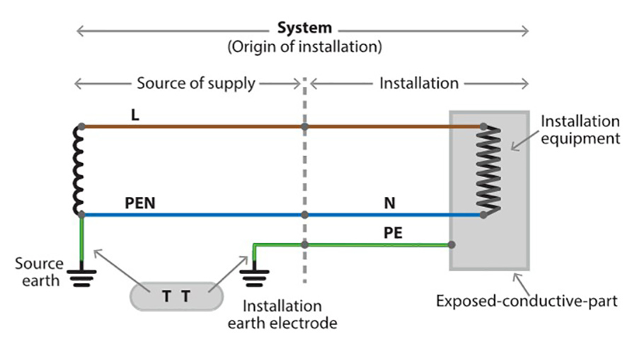
TT earthing facilities are installed when the distributor does not provide a TN earthing system or when circumstances dictate that a TN earthing system cannot be used. ‘T’ is French for Terra, which translates to earth. The first ‘T’ of a TT earthing system relates to the earthing of the distributors transformer, the second ‘T’ is the earth electrode installed at the consumers installation as shown in Figure 1.
Figure 1:
What is the method of protection against electric shock for TT systems?
For a TN system, automatic disconnection of supply (ADS) is the usual method of protection. The principle being that the low resistance earth loop and associated higher fault currents cause automatic disconnection within the required time. ADS can be used for TT systems providing a suitably low external loop impedance can be provided, but it is not usually the case.
Higher external earth fault loop impedances are usually associated with TT earthing systems, which don’t provide sufficient fault current to operate fuses or circuit breakers within the required time and an RCD must be used for electric shock protection.
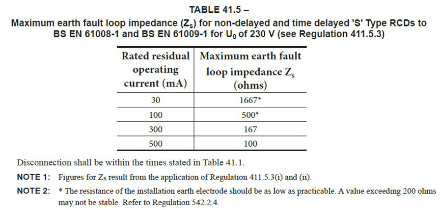
In order to fulfil the requirements of Regulation 411.5.3 of BS 7671:2018+A1:2020, the disconnection time shall be that required by Regulation 411.3.2.2 or 411.3.2.4 and RA × IΔn ≤ 50 V. The requirements of this regulation are met if the earth fault loop impedance of the circuit protected by the RCD meets the requirements of Table 41.5.
Table 41.5:
What types of electrode can be used for TT earthing systems?
Any of the electrodes identified below, taken from Regulation 542.2.2 of BS 7671:2018+A1:2020, can be used for a TT earthing system.
- Earth rods or pipes
- Earth tapes or wires
- Earth plates
- Underground structural metalwork embedded in foundations or other metalwork installed in the foundations
- Welded metal reinforcement of concrete (except pre-stressed concrete) embedded in the ground
- Lead sheaths and other metal coverings of cables, where not precluded by Regulation 542.2.5
- other suitable underground metalwork.
NOTE: Further information on earth electrodes can be found in BS 7430.
An earth rod is a simple and usually the most cost-effective method of providing an earth electrode. However, this may not be suitable for some installations and other types of electrodes may need to be considered.
Foundation metalwork embedded in concrete may be used as an earth electrode and can provide low earth resistance values, in some cases below 1 Ω. However, it is important to consider corrosion of the metal reinforcement, with respect to continuous leakage currents. DC earth leakage currents could cause corrosion and it may be necessary to consider cathodic protection.
See BS EN ISO 12696:2016 Cathodic protection of steel in concrete for further information on cathodic protection of steel in concrete.
What resistance values are required for a TT earthing system?
Table 41.5 of BS 7671:2018+A1:2020 states that 1667 ohms is the maximum earth fault loop impedance value where an RCD with a rated residual operating current of 30 mA is used. However, it is important to take into account the ‘*’ referring to note 2, which states the resistance of the installation earth electrode should be as low as practicable and a value exceeding 200 ohms may not be stable. But what does not be stable actually mean?
Note 2 of Table 41.5 refers to Regulation 542.2.4 of BS 7671:2018+A1:2020, which states ‘The type and embedded depth of an earth electrode shall be such that soil drying and freezing will not increase its resistance above the required value.’
The main factor affecting resistance to Earth of an earth rod is the depth of installation. It is appreciated that this information is difficult to obtain, but to mitigate the effects of the soil drying out, the earth electrode should be installed at a depth sufficient to reach the water table of the soil to remain effective.
What effect does temperature have on soil resistivity?
Temperature plays a big part in soil resistivity, when the ground freezes, the resistivity increases substantially. An earth electrode which is installed during moderate weather may become ineffective during winter.
Table 1 indicates typical resistance values per metre for various temperatures for assumed conditions of 15.2% moisture content sandy loam. If the soil temperature varies from 20c to -5c, the resistivity increases 10 times, from 72 Ω/m to 790 Ω/m. This is why the note referring to 200 Ω may ‘not be stable’ is so important.
Table 1:
|
Temperature |
Resistivity (Ω/m) |
|
20 |
72 |
|
10 |
99 |
|
0 (water) |
138 |
|
0 (ice) |
300 |
|
-5 |
790 |
|
-15 |
3300 |
What other factors affect soil resistivity?
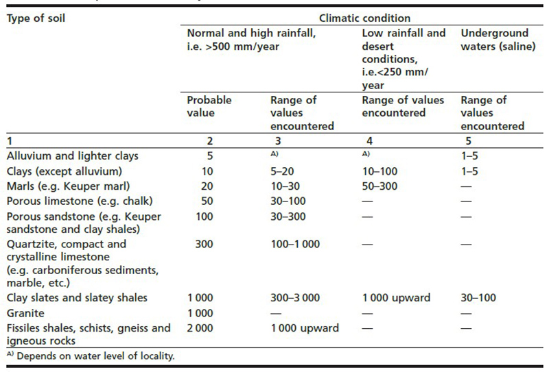
There are many factors that affect soil resistivity such as its physical composition, which is dependant on the geographical location. Geology maps can be consulted to determine what type of ground exists in different parts of the country. Table x indicates typical resistance values for different ground types. Other factors affecting soil resistivity include moisture content and chemical composition. Some minerals and salts can affect the resistance of soil and this may vary due to rainfall or the presence of flowing water.
Figure 2: Geological map of the UK
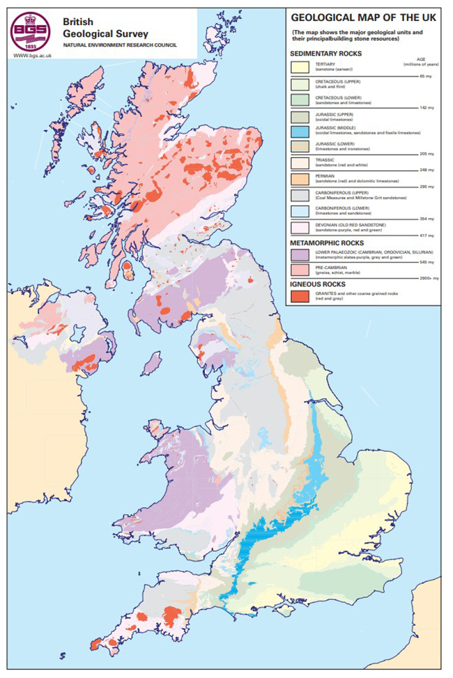
Table x: Examples of soil resistivity from BS 7430:2011+A1:2015 Code of practice for protective earthing of electrical installations
Where should an earth electrode be installed?
There are several important factors to consider when selecting the location for an earth electrode. It is important that the earth electrode is not installed in close proximity to other earthing systems, that are above or below ground.
Where above ground, special care must be taken to avoid simultaneous contact of conductive parts connected to different earthing systems as a potential difference may exist between both systems. In some cases, it may be necessary to convert the whole installation to a TT earthing system.
Below ground, adequate separation is required from buried metallic structures and pipes connected to PME earthing systems. It is important to check this distance with the distributor as it can vary but most distributors specify a value of either 2 or 3 metres. However, the problem is understanding where these buried items are located in order to understand an adequate distance.
Earth potential rise (EPR)
EPR occurs during an earth fault, the potential of the electrode and soil in the vicinity is raised close to nominal voltage until the protective device operates.
EPR in proximity to the earth electrode is an important factor which should be considered when installing TT earthing systems. It may be necessary to install a barrier to prevent contact by persons or livestock. This is especially important when wet barefoot persons or animals are in the vicinity. Animals are more susceptible to electric shock and it can only take a few volts to kill.
It might be worth considering that the distribution of ground surface potential in the vicinity of earth electrodes installed horizontally such as plates or rods are assumed to have smaller gradients than those of vertical electrodes. Further information on calculation of the fraction of earth electrode potential for horizontal electrodes can be found in BS 7430.
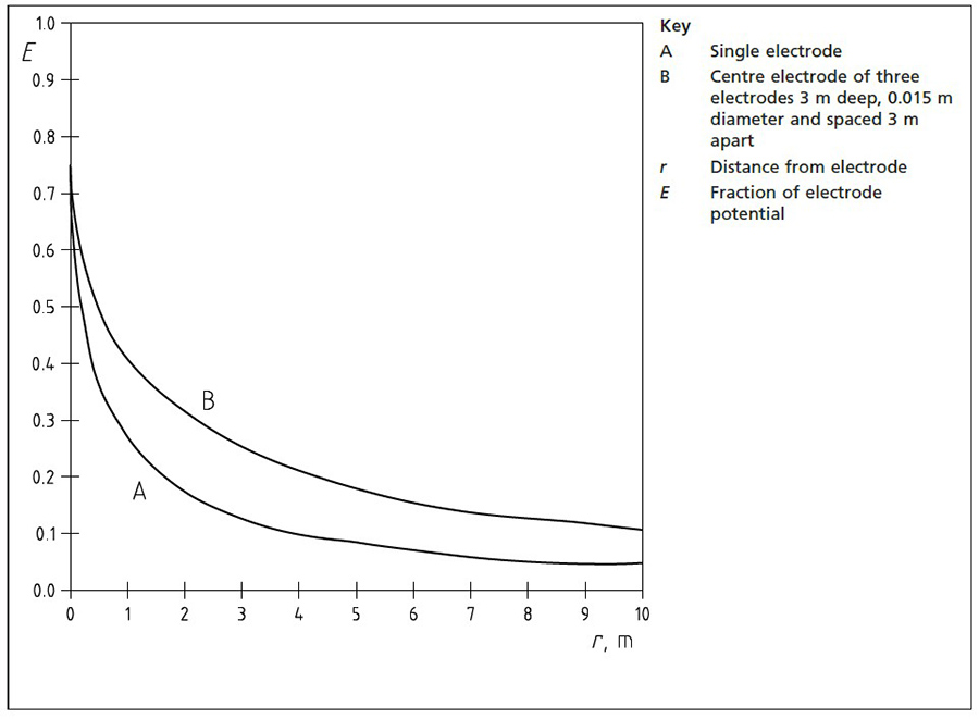
Two terms related to EPR are step potential and touch potential, step voltage is defined in the International Electrotechnical Vocabulary (IEV), as ‘voltage between two points on the Earths surface’ a note states that ‘typically, a distance of 1 m between the two points is considered to be the stride length of a human being’.
Figure 3 provides fraction of ground surface potential around a single rod and three rods in a line. It can be seen that for a single electrode within a radius of 1 metre, the fraction of potential would be less than 0.3 of the earth electrode potential.
Figure 3: Ground surface potentials around a single rod and three rods in line
What precautions should be taken before installing an earth electrode?
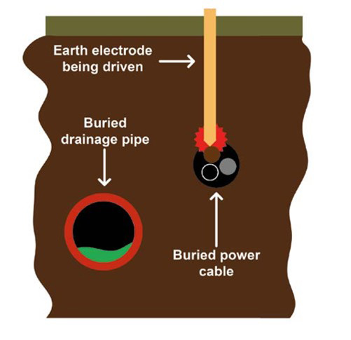
Prior to the installation of an earth electrode, it must be ascertained what could be buried underground, striking buried services could cause serious injury or incur significant repair costs.
Figure 4:
‘Dial before you dig’ is a free service available to anyone involved in construction and excavation, checking for utility assets in the vicinity of the proposed works. providing utility maps for cables and pipes. It is important to remember that this won’t include private cable and pipes installations on private land.
Cable avoidance tools (CAT) are available to purchase or hire and can be used to detect cables and pipes underground, it is important that the user understands how to use the equipment correctly. These devices are designed to identify metallic objects and will not detect pipes made from other materials such as, plastic or clay.
What alternative earth electrodes and installation methods exist?
Where any doubt exists regarding driving earth rods, an alternative method of installing an earth electrode may be to use an earth mat or plate as it is referred to in BS 7671:2018+A1:2020. Earth plates are typically 600 mm x 600 mm x 3 mm and can be of lattice construction as seen in Figure 5.
Figure 5:
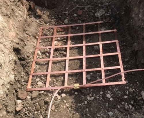
A hole is required to be excavated to install an earth mat and backfilled on completion. It is important to ensure they are buried at a suitable depth to avoid drying out or freezing of the soil, this is usually at least 600 mm depth.
The benefit of this type of electrode is the hole can be hand dug using an insulated spade to minimise the risk of damage to services.
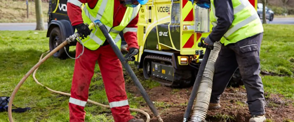
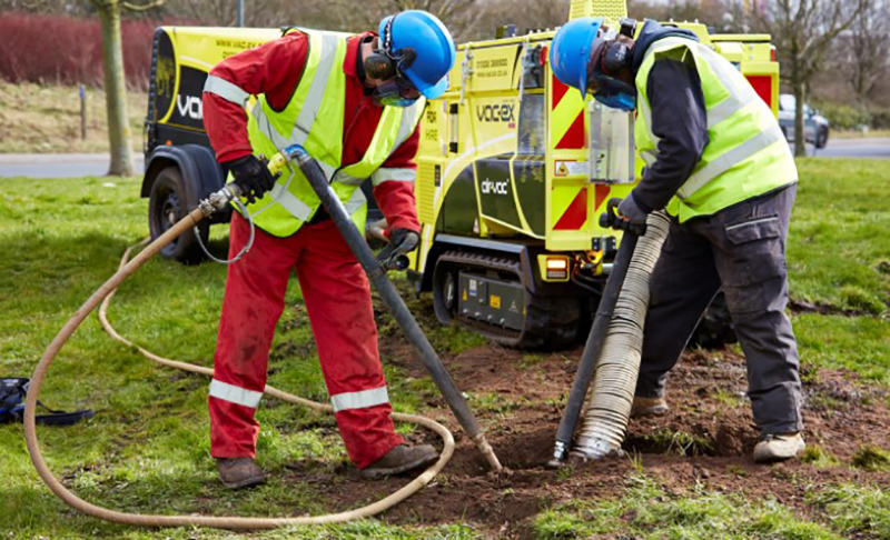
Another method is vacuum excavation, which is basically a large vacuum cleaner that uses compressed air and powerful fans to create a vacuum to remove the material from the ground, eliminating the risk of mechanical damage to services. At first this might seem like a costly option but when compared to serious injury or repair bills for services it is definitely worth consideration.
Figure 6:
Does an earth electrode require maintenance?
An earth electrode doesn’t require maintenance as such, but it does require periodic inspection and testing to verify it is suitable for continued use. It is good practice to plan the testing regime to take place at different times of the year to take into account seasonal variation affecting soil resistivity. It is generally accepted within the lightning protection industry for testing to take place every 11 months for this reason.
Summary
TT earthing systems are a safe and effective method of earthing and can be a good solution when the risks associated with PME earthing systems are unacceptable.
Careful consideration and planning is required when installing TT earthing systems or a hazardous situation could be created.
Engineering Networks Association (ENA) Engineering Recommendation G12/4 requires a TT earthing system for fuel filling stations, caravans and boats.
For further information on fuel filling stations, please see IET Wiring Matters article 'Special locations: Filling stations' [PDF, 4MB] and APEA/EI Guidance for Design, Construction, Modification, Maintenance and Decommissioning of Filling Stations, more commonly known as the ‘blue book’.
Installing a TT earthing system is not a case of fit and forget, periodic inspection and testing is required to verify the protective measures are still effective and taking into account seasonal variations.
BS 7430:2011+A1:2015 Code of practice for protective earthing of electrical installations provides further information on earth electrodes.