
Back to the Forum - Current-carrying capacity of cables buried in the ground
The question is, ‘what is the difference between manufacturer’s data and BS 7671?’ In this article we look at the information available and why the information is perceived as different.
What are the effects of installing a cable in the ground?
Where a cable is buried in the ground its ability to dissipate heat is reduced, the extent of which depends on the installation method. Typically, cables installed in ducts will need to be larger than those buried direct in the ground as the air surrounding the cable is heated by thermal radiation from the cable, reducing heat dissipation.
How do I select the current-carrying capacity for a cable buried in the ground?
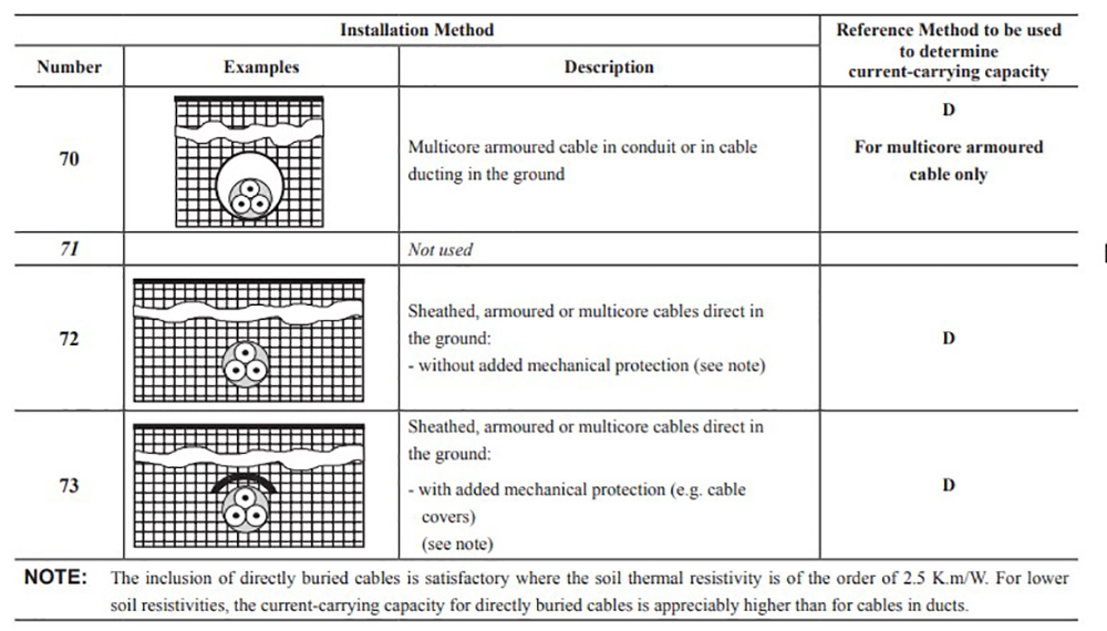
BS 7671:2018+A1:2020 provides tabulated current-carrying capacity values for common installation methods. If cables are buried in the ground, either direct or inside ducting, reference method D (Figure 1) is applicable and the appropriate value should be selected according to its type from the relevant table identified in Appendix 4.
The installation method takes into account assumed parameters, such as ambient ground temperature (Ca), soil thermal resistivity (Cs), depth of laying (Cd) and spacing factor (Cg), the correction factors for which can be found in Tables 4B2, 4B3, 4B4 and 4C2 respectively.
It is important to remember that it is unlikely the cable will be buried throughout its entire length, at some point the cable will exit the ground to be terminated, where it will no longer be buried in the ground and a different reference method will also need to be considered.
Figure 1
What if the cable or installation method is not included in BS 7671?
Not every installation method is provided in BS 7671, as there are too many permutations. There are certain types of cables and installation methods that are not identified and the electrical designer must make an engineering judgement or carry out bespoke calculations.
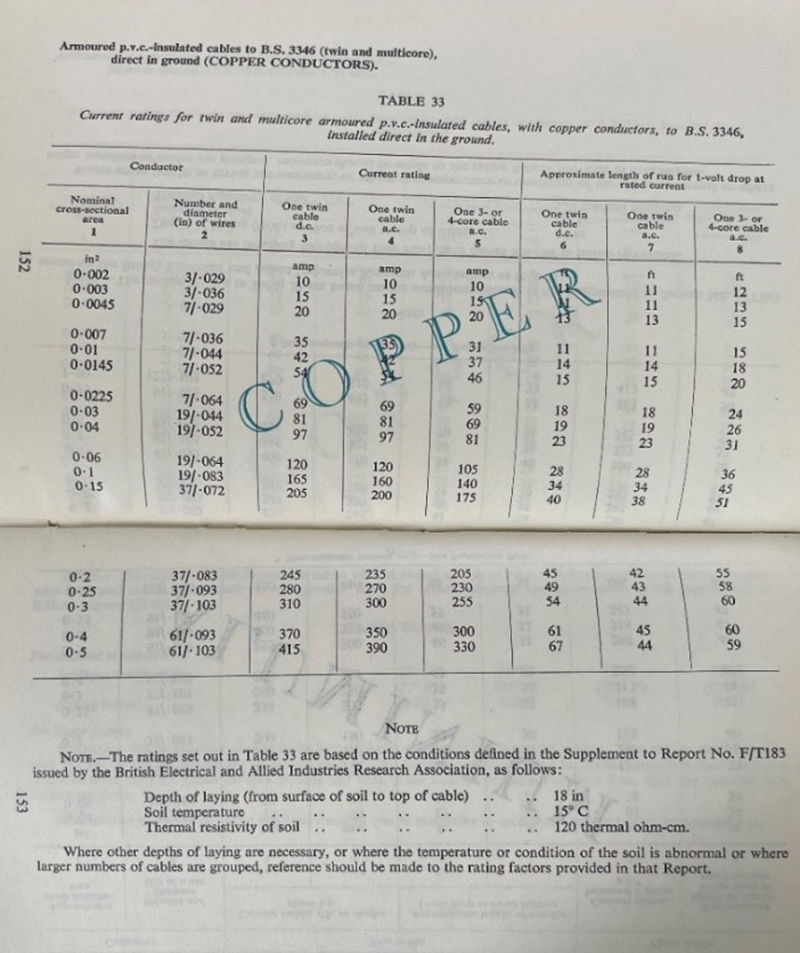
Traditionally, tabulated values were not provided in the IEE Wiring Regulations, the current-carrying capacity ratings for cables buried directly in the soil first appeared in the 13th Edition of the IEE Wiring Regulations in 1955 as seen in Figure 2. Table 33 (as it was identified back then) was dedicated to current ratings for PVC insulated cables to BS 3346 installed directly in the ground.
Figure 2: extract from the Thirteenth Edition of the IEE Wiring Regulations
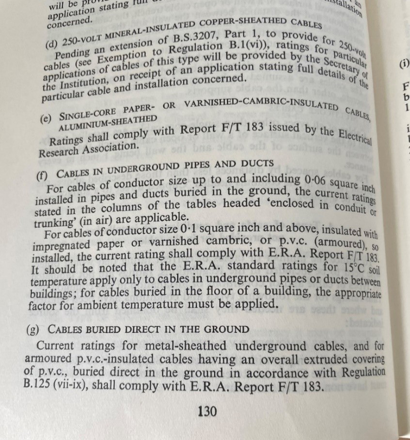
However, the tables were not included in the next publication, the Fourteenth Edition of the IEE Wiring Regulations in 1966 but, instead, stated that current ratings shall comply with ERA report F/T 183 as seen below in Figure 3.
Figure 3: extract from the Fourteenth Edition of the IEE Wiring Regulations 1966
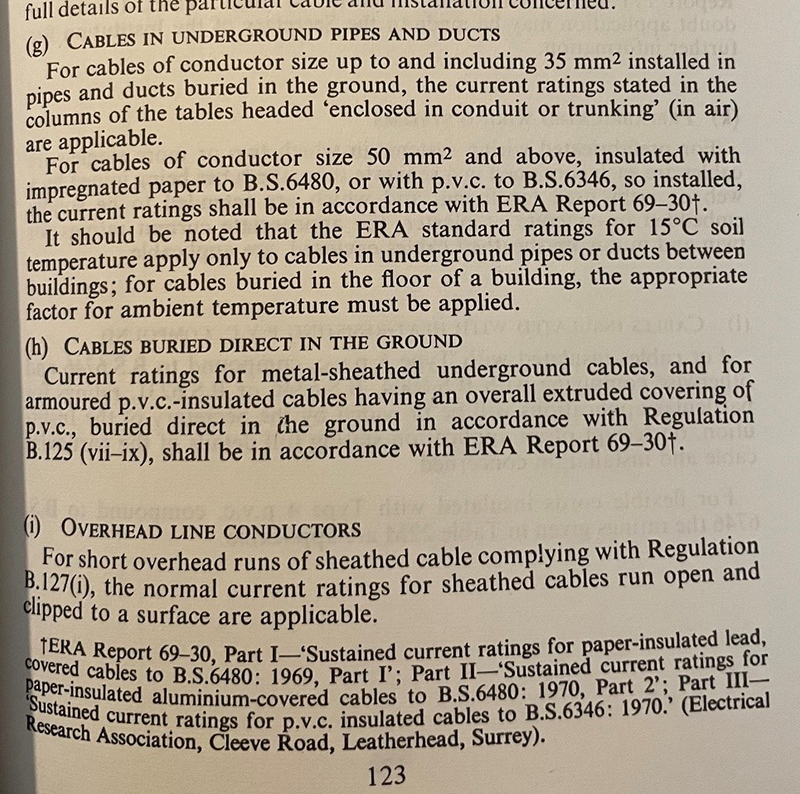
Later, in the reissued Fourteenth Edition of the IEE Wiring Regulations incorporating Amendments 1970, 1974 and 1976 including metric units, it was stated that current ratings shall be in accordance with ERA report 69-30 as seen below in Figure 4. It was not until the Seventeenth Edition of the IEE Wiring Regulations in 2008 that tabulated values were reintroduced as Table 4D4A (thermoplastic) and Table 4E4A (thermosetting).
Figure 4: extract from the Fourteenth Edition of the IEE Wiring Regulations 1966 incorporating Amendments 1970, 1974 and 1976
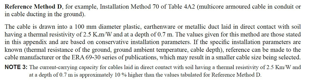
The ERA 69-30 series are still referred to in BS 7671:2018+A1:2020 today. Appendix 4 of item 7.1 reference method D states ‘if the specific installation parameters are known (thermal resistance of the ground, ground ambient temperature, cable depth), reference can be made to the cable manufacturer or the ERA 69-30 series of publications, which may result in a smaller cable size being selected.’ as seen in Figure 5.
Figure 5
What are the ERA 69-30 series reports?
The ERA was commissioned to produce a series of reports on the current-carrying capacities of cables. The series of reports are called the ERA 69-30 series, previously called F/T183 and first published in 1955 have been referred to in the IEE Wiring Regulations for many years.
There are nine parts to the ERA 69-30 report series, covering different types of cables and installation methods. Part III of the ERA 69-30 provides values of current-carrying capacity and calculation methods for, ‘sustained current ratings for 600/1000 V and 1900/3300 V cables with 70°C thermoplastic insulation (ac 50 Hz and dc).’ The values of current-carrying capacity tabulated in the report are in accordance with IEC 60287 Electric cables - Calculation of the current rating.
The ERA series of reports are still available and can be purchased by emailing RINA at ukinfo@rina.org.
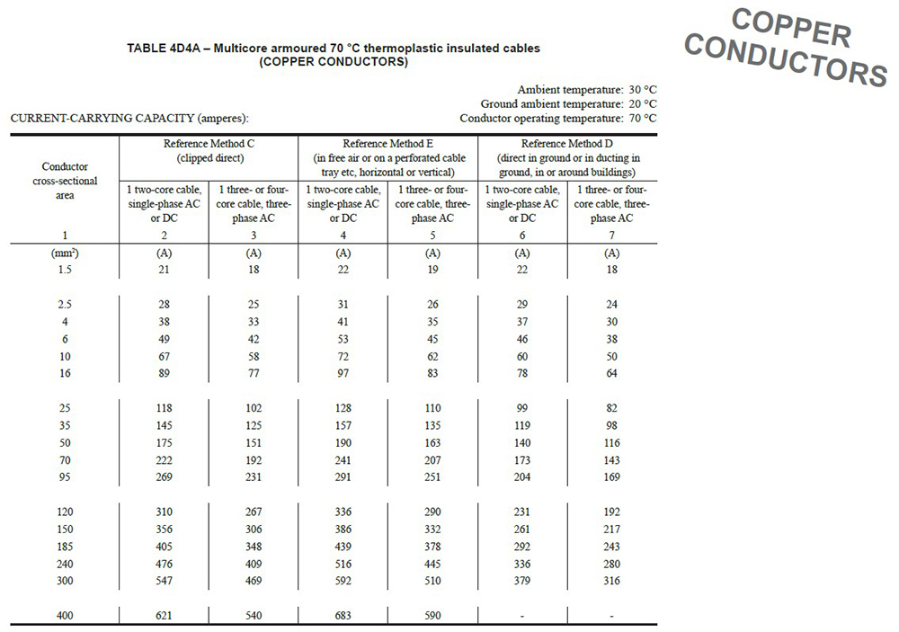
An important note in the ERA 69-30 report Part III, states ‘cables installed in and around buildings subject to the provisions of the IEE Wiring Regulations, BS 7671, should be rated in accordance with those Regulations.’, which is probably where the ‘in or around buildings’ comes from in the description under reference method D in Table 4D4A as seen in Figure 6.
Figure 6
What is soil thermal resistivity?
Thermal resistivity of soil is different to soil resistance. Soil resistance is the ability to pass electrical current, which is relevant to earthing systems. The thermal resistivity of soil refers to its ability to dissipate heat, which is relevant to the current-carrying capacity of cables.
Soil resistivity is affected by many factors including geographic location, soil composition and water flow and it will also change seasonally. It is important to consider that if the cables are supplying a continuous heavy load, this can cause the soil to dry out and increase the thermal resistivity.
Note the unit used for thermal resistivity of the soil in the Thirteenth Edition of the IEE Wiring Regulations was thermal ohm-cm as seen in Figure 2. Today we use K.m/W, Kelvin Metre per Watt, 120 thermal ohm-cm converts to 1.2 K.m/W (120/100 = 1.2). These values were based on the conditions identified in the supplement to Report No. F/T 183 issued by the ERA.
What are typical values of soil thermal resistivity?
By the time tabulated values for buried cables were reintroduced in the Seventeenth Edition of the IEE Wiring Regulations in 2008, the IEE Wiring Regulations had become a British Standard, BS 7671:2008, based on the European CENELEC HD 60364 series of standards. HD 60364-5-52 Selection and erection of electrical equipment. Wiring systems, states a general value of 2.5 K.m/W is considered necessary as a precaution for worldwide use when the soil type and geographical location are not specified.
The ERA 69-30 report assumes a soil thermal resistivity of 1.2 K.m/W, which corresponds with typical soil thermal resistivity for the UK in Annex A (A.22.2) of BS IEC 60287-3-1 Electric cables - Calculation of the current rating: Operating conditions - Site reference conditions, although this is considered to be a broad-brush statement.
It is important to remember that the testing carried out for the ERA 69-30 reports was under controlled conditions and using consistent backfill material, for example, in the real world it is much different.
Cement bound sand is a product that is available and can be used as backfilling material to ensure the thermal conductivity is of a known value and will remain consistent for the lifetime of the cable. However, this is unlikely to be a cost-effective option for smaller CSA cables when compared with using a more conservative cable size.
Why are cables selected smaller when using manufacturers’ cable data?
Typically, electrical design software is used for cable selection on larger installations. Some electrical design software packages specifically refer to ‘BICC cable data’ but other manufacturer’s data also exists, other software packages refer to ‘ERA 69-30’. Most cable manufacturers data is based on the values used in the ERA 69-30 series but not all, so it is worth checking.
Issues can arise when manufacturer’s cable data has been used by a consultant to complete the design, but when checked by the contractor against tables in BS 7671 directly, the sizing can appear to be inadequate. However, when the appropriate correction factors are applied, the results will be the similar as they are based on calculation methods derived from IEC 60287 Electric cables - Calculation of the current rating. The assumed values for each publication are identified in Table 1 below, the main influencing factor is the soil thermal resistivity.
Table 1
|
|
BS 7671 |
ERA 69-30 |
Correction factor (Table) |
|
Ca Ambient ground temperature |
20oC |
15oC |
1.05 (4B2) |
|
Cs Soil thermal resistivity |
2.5 K.m/W |
1.2 K.m/W |
1.40 (4B3) |
|
Cd Installation depth |
0.7 m |
0.5 m |
1.03 (4B4) |
The values used for calculation will depend on the actual ground conditions and material used for backfilling. The electrical designer must choose which is the most appropriate and apply the relevant correction factors. Unless specific values can be obtained, using the values direct from BS 7671 could be considered a safe option for the electrical designer.
When considering energy efficiency and the cost associated with a cable throughout its lifetime, it is important to remember that a smaller CSA cable will have higher energy losses (I2R), when compared with larger CSA, this is because more heat is dissipated.
Other considerations
There are other considerations to be taken into account by the electrical designer when selecting a suitable CSA of cable, such as length, voltage drop, energy let through (I2t) from the protective device and thus the energy withstand rating of the cable.
Summary
The current-carrying capacities of cables buried in the ground used in BS 7671:2018+A1:2020 and the ERA 69-30 report series are derived from the same calculation methods identified in the relevant parts of IEC 60287.
The current-carrying capacities published in BS 7671:2018+A1:2020 are based on tabulated values in HD 60364-5-52, whereas the current-carrying capacities used for manufacturers’ data are based on the ERA 69-30 report series. The assumed values for ambient ground temperature, soil thermal resistivity and installation depth used in each publication are different which will result in a different cable size being selected. If the appropriate correction factors are applied, the results will be the same.
Unless specific details are known, the electrical designer should use the tabulated values provided in BS 7671:2018+A1:2020. Reference method D of BS 7671:2018+A1:2020 should be applied for cables buried in the ground in and around buildings.
It is the electrical designer’s responsibility to apply the appropriate factors to ensure the cable is sized adequately, it would not be deemed acceptable to blame the electrical design software for any errors.