
The framework for energy efficiency in electrical installations
Energy efficient design and control as a process
The international standard IEC 60364-8-1 Low Voltage electrical installations – Part 8-1: Energy Efficiency provides a system diagram which provides an overview of the various energy sources and control inputs to an electrical installation. Analysis of this shows how energy efficient electrical installations should have an optimum energy path and a comprehensive control path.
The purpose is to ensure that the electrical infrastructure is designed to safely support the load whilst being located correctly and minimise unnecessary losses in the distribution system. The controls should be configured to ensure the electrical installation operates when the user requires it, whilst also minimising wasted energy consumption when the user is away. There are two key areas to consider when designing and operating an energy efficient electrical installation: the energy path and the control path. How these are set up and work together will determine how successful the efficiency will be.
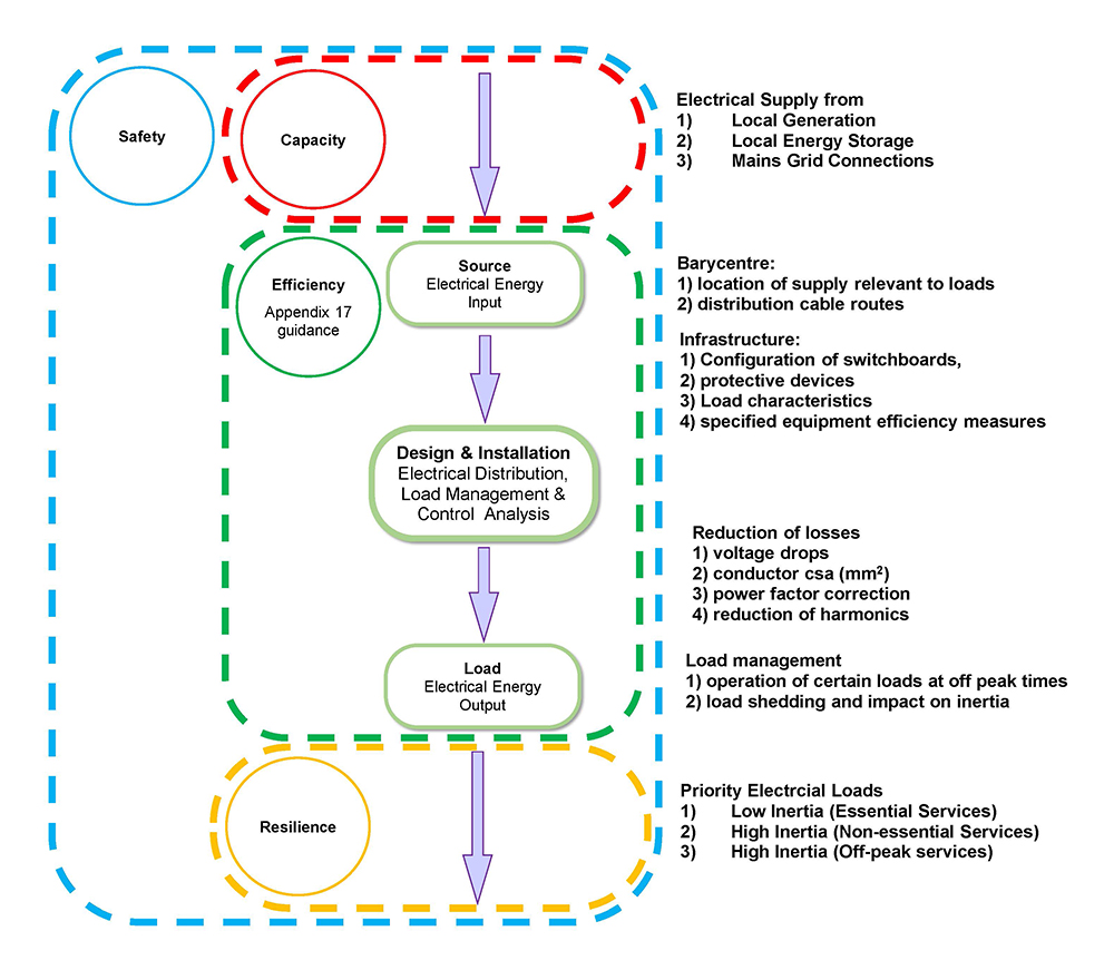
The energy path is from the main intake through the main switchgear, distribution infrastructure and finally to the point of use e.g., a fixed electrical machine, water heater, luminaire, socket outlet. Historically the electrical supply would always be from a grid connection and some specialist installations, such as hospitals, would also have a standby generator for essential services.
Now electrical supplies may come from multiple sources including from a traditional grid connection, or via local onsite generation (including wind turbines or photovoltaic), or perhaps local on-site energy storage facilities. With careful controls an optimized installation may use a combination of all these supplies. Monitoring of these energy sources allows users to adjust their requirements, or to deploy automatic controls, and optimize the energy to the electrical installation. For those installations with standby generators there could also be revenue opportunities, through special contracts, to supply their electricity at times of peak demand on the mains electrical grid.
Electrical distribution systems should be carefully designed to avoid wasted energy. Using a barycentre approach to locating the supply near to distribution switchboards and onwards to electrical loads can reduce copper infrastructure costs and lower energy losses too. In practice energy efficient distribution means the point of supply should be as close as possible to the point of use. The reality is that a DNO will invariably provide a supply on the boundary of a site sometimes far from the point of use. For larger sites there may be opportunities to negotiate this with the DNO to provide a compromise solution.
An analysis of electrical load power factor and harmonics is necessary. Local measures to deal with this, instead of a centralized approach at the main intake, can improve the overall site efficiency. Adverse effects from power factors and harmonics also reduce efficiency and ideally should be dealt with at the point of use, especially with larger loads such as chillers and air handling units. Ensuring that electrical cables are correctly sized has always been necessary to improve safety and reduce fire risks. Correct cable sizing will also mitigate the effects of harmonics, although the connection of filters may be required.
The concept of load inertia describes the load’s reaction to first being switched off to shed load and subsequently being reinstated; however, this may have consequences and effects on the levels of service to the end users.
For example, from an energy efficiency perspective, shutting down a large or complex plant for only a short period could be counterproductive, as it would require more energy to bring it back up to speed than was saved by shutting it down. This load would be known as a low inertia load. Other examples may include:
- Manufacturing machinery with fine tolerances might not respond well to a loss of power either to save energy at peak times or though line faults.
- Safety critical loads could be described as low inertia loads and should not be used to shed load and save energy. They should ideally have UPS back up too.
On the other hand, most LED lighting installations would be known as high inertia because of their ability to energize quickly after an interruption on supply. Some older lighting technologies, such as those using inert gas, would be low inertia because they need to cool down sufficiently before being reused.
Instantaneous water heaters would be high inertia because they will operate satisfactorily as soon as the electrical supply is restored. Other hot water systems using storage tanks are by definition low inertia because of the length of time it takes to reheat. However, for short interruptions in supply they might be largely unaffected.
Operating characteristics of electrical loads can be varied too. They will react differently to a temporary loss of power and subsequent reinstatement of supply. This can affect their response to load management when an installation’s maximum capacity is reached (ability to load shed) or pause operation when if electrical tariffs change adversely.
The energy path below shows the energy sources through the electrical installation and on to the point of use – the electrical loads.
Figure 1: Energy Path
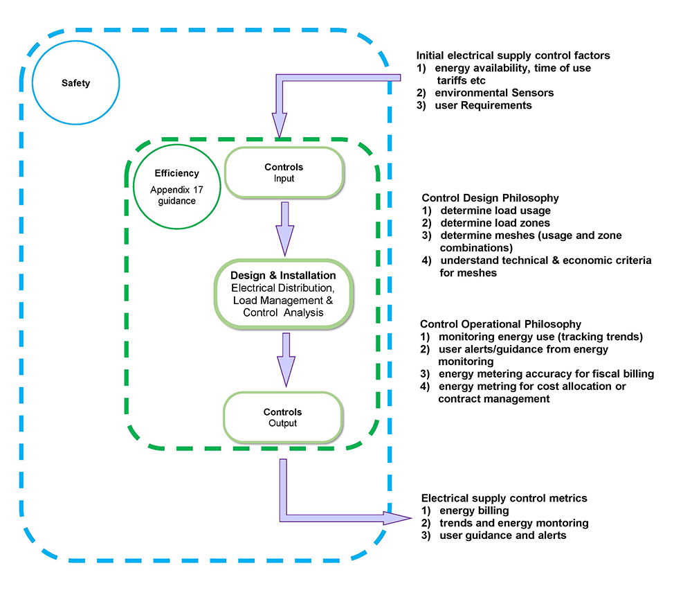
The control path shows the influence of the control inputs on the use of energy through the energy management systems and on to any control outputs such as billing or just user feedback interfaces.
Control inputs to an electrical installation are increasingly important in a modern installation. They provide analysis, in real time, of the environmental conditions, the availability of different types of electrical energy source and the local demand.
Electrical energy demands need to be controlled as much as possible at the point of use and should respond to local requirements when the area is occupied. Whilst automatic controls should be considered to optimize energy-efficient operation, where necessary the needs of end-users must be taken into account. Local override controls may be necessary, for instance on lighting or local direct electrical heaters in certain situations. Occupancy detectors can reset the system from manual control back to automatic control to prevent wasted energy.
Influences on controls might be the availability of an energy source, the energy tariff (cost) at any particular time of day, automated responses to changes in environmental conditions or the need of the end-users to use the space differently from the predefined automated settings (controls override).
Controls design philosophy should respond to how the building is to be used:
- what is being used – types of loads or usage
- where it is used – zones
- integration of load types and geography – meshes
- technical constraints and risks
- economic requirements
The controls philosophy of an energy-efficient electrical installation should provide a number of outputs that enable the user to monitor performance of usage, zones and meshes, and then make informed decisions to improve those operations. Three key outputs would be:
- trends and monitoring – as an energy management tool to track normal and abnormal energy use
- energy billing – using appropriate fiscal meters only to track energy costs and cost recovery in multi-user installations
- user guidance or alerts – using controls to assist with first-line maintenance monitoring and local alerts of equipment still in use when not needed.
Operational requirements for controls should be carefully considered. The outputs from control systems can assist with monitoring energy consumption. Tracking trends can highlight wasted energy consumption and areas for improvement. Energy monitoring can provide granular details of usage in various cost centres and assist with local billing mechanisms.
Controls are an integral part of electrical energy efficiency; however, it is important to note that:
- they should not compromise safety
- they should respond to user requirements. Overrides to automatic energy efficiency controls to adapt to immediate user needs may be necessary.
Critically, all energy efficiency controls should still be subject to safe systems of work and work in conjunction with normal electrical isolations for the purposes of reactive and planned maintenance. Safety remains of primary importance and any measures taken to make an electrical installation more energy efficient must not compromise the safety of any occupants, property or livestock.
Likewise, efficiency of an installation should not impair the acceptable levels of service for a user or the availability of an electrical supply at times of maximum demand.
The control path in Figure 2 shows the influence that controls will have on an electrical installation from the point of supply, through the infrastructure to the point of use.
Figure 2: Control path
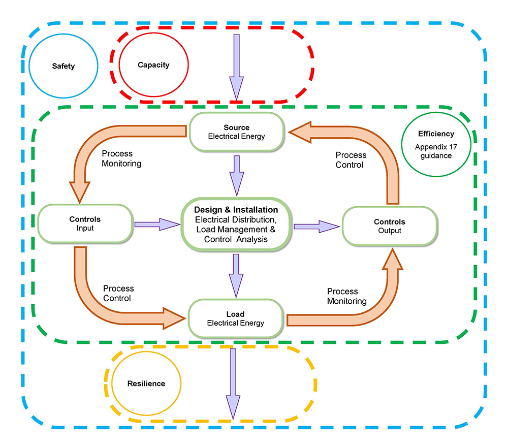
The energy path and the control path interact closely and integrate as a typical circular “plan, do, check act” process: energy input at the top, control inputs on the left, energy outputs on the bottom and control outputs on the right.
From top to bottom the requirements of an energy efficient design can be fulfilled ensuring that the electrical distribution and electrical installation are satisfactory and meet the necessary criteria. From left to right, the control process ensures that control over energy consumption is carefully considered and correctly commissioned.
An ongoing control sequence of process control and process monitoring should ensure that electrical energy efficiency is optimized and has the opportunity to be gradually improved. Maintenance activities are periodic checks on the continued safe and satisfactory operation of an electrical installation. It should also be a check on the operational efficiency of the electrical installation and a reminder to recommission as necessary.
Figure 3: Process
Other design tools and techniques
Load management
The designer, in the early stages of the project, should consult with key stakeholders, such as the client and end user, to categorize relevant zones, usage and meshes throughout the electrical installation to identify opportunities for energy efficiency.
- Zones: this identifies where electrical equipment or appliances will be used. Typically based on the geography of the building, for example a paint shop in a factory, main staircase or corridor in a building, a zone could be controlled as one entity and switched off without necessarily impacting on the use of neighbouring zones.
- Usage: this identifies what type of appliances, or particular electrical loads, will be operated not just in any one zone but across the whole installation. IEC 60364-8-1 identifies the largest electrical consumer usages as:
- hot water production
- heating, ventilation and air conditioning
- lighting
- motors,
- appliances.
The designer should use the consultation period to ensure that all major loads are identified in respect of their rating (kW) and their hours of operation.
- Meshes: this identifies what common control inputs will be provided for electrical equipment. This could be across one or more zones with one or more usages. An example could be interleaved lighting circuits in adjacent hospital corridors, with separate zones, single usage, multiple circuits and one mesh for energy efficiency purposes.
Meshes are an important component with any electrical energy efficiency regime. Another example could be a hotel suite with a bedroom being one zone and a bathroom being another. Various usages can be identified in both spaces. However, an energy saving control system by the rooms main entrance will simultaneously switch off agreed circuits, with a number of usages, as the occupant withdraws their card key. Another mesh, though, will retain power to other circuits such as the fridge that should not be switched off or some lighting for reassurance.
IEC 60364-8-1 describes a number of criteria that are relevant to the development and implementation of meshes. Ensuring these criteria are all considered correctly demonstrates the efficiency of the installation. Using these criteria the designer must consider how the installation loads will be managed to optimize the electrical energy efficiency measures. This includes responding to:
- defined time controls to stop certain loads at certain times, or moderate maximum demand, or run at off peak periods
- daylighting in the case of lighting especially externally and near windows
- external temperature in the case of electrical heating
- wasteful switching by the occupants (occupancy detection)
- the connection of loads (absence detection)
- switching using inputs from external sources (environmental sensors, thermostats, humidity sensors, air quality sensors).
Load management, using meshes, is the process by which the electrical supply to the installation is distributed to the connected loads. These may have multiple usages and be located across several zones. To be energy efficient the load management process will activate them at the right time, with appropriate automated controls and measurements, to optimize the use of the energy and reduce wasted energy.
Purpose of electrical meters
The deployment of electrical meters throughout the installation will assist with both Building Control compliance (Approved Document Part L) and operational energy efficiency through the lifetime of the installation. Electrical designs should consider metering for fiscal purposes at the head end of the installation and for energy management.
Fiscal metering for electrical supplies for larger installations will be subject to half hourly monitoring. This data can be requested as an aid assess energy consumption through certain points of the day or week. This information in turn can aid improvements in energy efficiency.
On smaller installations analysis of just the main intake energy meter may be justified. However, on more complex installations with multiple tenants or internal departments, it will be necessary to provide load profile analysis closer to the point of use at sub-distribution level. In Part L of the UK Building Regulations new installations over a certain size require 90% of the installation to have specific sub-meters. The use of meters throughout the installation demonstrates the ability to closely control the load and will score additional points in the design appraisal of the electrical installation. It will improve the operational efficiency of the installation too
Sub-meters should be embedded throughout the installation to:
- measure and record the load profile for the installation to understand when the energy is being used during set periods, for zones, usage or meshes, and
- measure the load characteristics to understand what effect the load has on efficiency of the incoming power supply infrastructure. This involves periodically measuring the demands placed on the supply by the electrical loads’ power factor, energy consumption, current, voltage and harmonics.
IEC 60364-8-1 cross references several other standards to define the type of meters that would be used at different parts of the installation and the level of information that may be required.
Ethernet connections for embedded metering systems enable all meters to be monitored remotely and data to be collected. This allows loads to be analysed in real time and monitoring of trends and patterns of load behaviour. Result of this analysis can influence when the load is connected to the grid and hence use cheaper electrical tariffs where possible or load shed non-essential loads at times of supply constraints.
Some electrical meters assist with power quality analysis (PQA). This is important for understanding power factors and harmonics and the associated energy losses with these aspects. Harmonics caused by non-linear loads are a major concern. Measuring power quality is important so a solution can be provided where harmonic distortion is found.