
Earth leakage

One question being asked in the IET Engineering Communities Forum is ‘Earth Leakage Current – How much is too much?
This question is being asked more often due to the proliferation of electronic equipment.
What is Earth leakage current?
Earth leakage current is not specifically defined in BS 7671:2018+A1:2020, it is referred to as protective conductor current. Protective conductor current is defined as an ‘electric current appearing in a protective conductor, such as leakage current or electric current resulting from an insulation fault.’
Leakage current is also defined as ‘electric current in an unwanted conductive path under normal operating conditions.’
Earth leakage current can exist through an insulation fault in cables or equipment, or it can occur under normal operating conditions in electronic equipment which use capacitors for filtering purposes in power supplies which can cause leakage to Earth when functioning.
Hence this type of equipment requires a functional earth, which is different from a protective earth.
What are the effects of leakage current?
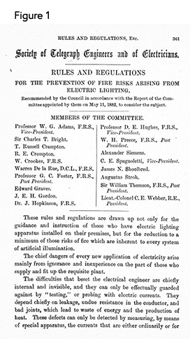
The extract in Figure 1 is taken from the First Edition of the IEE Wiring Regulations in 1882 and it can be seen that leakage current was a consideration even back then, although probably for different reasons. It could be said that the First Edition was more concerned with waste of energy and heat than electric shock.
‘The difficulties that beset the electrical engineer are chiefly internal and invisible, and they can only be effectually guarded against by "testing" or probing with electric currents. They depend chiefly on leakage, undue resistance in the conductor, and bad joints, which lead to waste of energy and the production of heat. These defects can only be detected by measuring, by means of special apparatus, the currents that are either ordinarily or for the purpose of testing, passed through the circuit.’
In 1882 unwanted tripping of RCDs would not have been an issue, today with most circuits requiring RCD protection for one reason or another, and the proliferation of appliances containing electronic equipment, unwanted tripping is a real issue.
How can Earth leakage/ protective conductor currents be measured?
One way of measuring earth leakage is to use a leakage current clamp ammeter. Leakage current clamp meters are similar to those used for measuring load current, but are more sensitive and therefore more accurate at measuring currents below 5 mA.
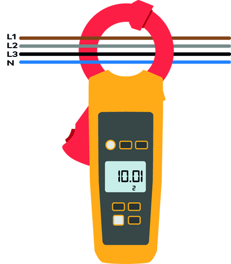
To determine the Earth leakage on the whole installation, place the clamp around the live conductors for the installation a shown in Figure 2 for single phase, or Figure 3 for three phase installations.
Figure 2
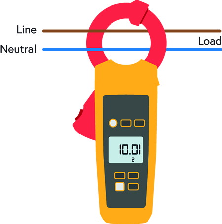
Figure 3
In the case of an installation that does not have any leakage current, the reading should be zero as the currents should cancel each other out, if any current is leaking to earth, the value will be displayed on the instrument. If leakage current is identified in the installation, it will be necessary to isolate and test individual circuits in order to identify those that are affected.
To determine if the Earth leakage current is within the installation or from the equipment, it is necessary to isolate current using equipment from the installation and use the clamp ammeter to test each individual item separately. Place the clamp around the live conductors for the installation a shown in Figure 2 for single phase, or Figure 3 for three phase installations
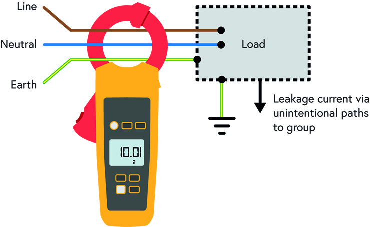
It could be that the leakage current is returning to Earth directly and not returning via the earthing conductor. To determine if any leakage current is returning via fortuitous connections with Earth, the clamp ammeter can be placed around the line, neutral and protective conductors as shown in Figure 4.
Figure 4
Insulation resistance vs insulation impedance
It is worth noting that taking a measurement of leakage current and using the value to carry out an ohms law calculation will provide the value of insulation impedance. The result will be different from the value of insulation resistance which is obtained from an isolated circuit using an insulation resistance tester. The reason being the insulation resistance tester applies a DC voltage test that does not take account of the capacitance of the circuit. It is the insulation impedance value which actually exists under operating conditions.
What about DC leakage current?
Measuring DC with a clamp meter is not as simple as measuring AC. At present, there are not any clamp ammeters which can measure DC leakage current to any degree of accuracy.
Residual DC leakage current can cause blinding to AC type RCDs, see IET Wiring Matters article Which RCD type? for further information.
What does BS 7671:2018+A1:2020 say about unwanted tripping?
Regulation 314.1 of BS 7671:2018+A1:2020 requires an installation to be divided into circuits, as necessary to, ‘reduce the possibility of unwanted tripping of RCDs due to excessive protective conductor (PE) currents not due to a fault’.
Regulation 531.3 of BS 7671:2018+A1:2020 provides the requirements for Residual current devices (RCDs). Regulation 531.3.2 states that residual current protective devices shall be selected and erected such as to limit the risk of unwanted tripping. Indent (ii) states that the accumulation of such currents downstream of the RCD shall be not more than 30 % of the rated residual operating current. So, assuming we are using an RCD with a rated operating current of 30 mA, the maximum leakage current is 9 mA.
Note 2 of Regulation 531.3.2 states that RCDs may operate at any value of residual current in excess of 50 % of the rated residual current. If unwanted tripping of an RCD protecting several circuits is experienced, it could be a cumulative effect of the leakage current of the protected circuits.
Regulation 543.7 recognizes earth leakage currents in excess of 3.5 mA as high protective conductor currents. Specific additional protective measures are required for circuits considered to have high protective conductor currents.
Other causes of unwanted tripping
In some cases, unwanted tripping could be caused by RCDs or RCBOs which are too sensitive, this can be determined with an RCD ramp test. An RCD with a residual operating current of 30 mA could trip anywhere between 15 mA and 30 mA, typically it will operate at 75 % of IΔn.
How does current leakage occur within electronic equipment?
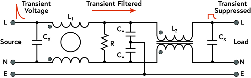
Leakage current in electronic circuits is typically from power supplies. This is due to the use of capacitors used to filter transients from the supply. Electrical transients are short bursts of energy with potential to damage electronic circuits. Figure 5 illustrates the filter capacitors connection to earth, which is the route for the leakage current.
Figure 5
What are typical equipment maximum earth leakage values?
BS EN 60335-1 provides the general safety requirements for household and similar electrical appliances. Maximum values of earth leakage for appliances are identified below, it is important to remember these are maximum values:
- For class II appliances and for parts of class II construction - 0.25 mA.
- For class 0, 0I and III appliances: 0.5 mA b for class I portable appliances -, 0.75 mA.
- For class I fixed motor-operated appliances - 3.5 mA.
- For class I fixed heating appliances - 0.75 mA or 0.75 mA/kW of rated power, with a maximum of 5 mA, whichever is the higher.
The amount of leakage current will vary according to the type of equipment. The IEC 60335 series of Standards provides requirements for different types of products:
- Fixed PC workstation - 2 mA
- Printer - 1 mA
- Photocopier - 1.5 mA
- Laptop - 0.5 mA (with EMC filter)
- Grills, toasters/portable cooking appliances - 0.75 mA (earthed metal)
- Fridges - 1.5 mA (class I)
- Dishwasher - 5 mA
- Hobs, ovens - 1 mA or 1 mA/kW of rated power
- Washing machine - 5 mA
- Tumble dryer – 5 mA
- Electric heat pumps - 10 mA (accessible to public)
- Floor heating - 0.75 mA or 0.75 mA/kW of rated power
Luminaires can also be a source of leakage current, BS EN 60598-1 provides the leakage current requirements for Luminaires:
- Continuous interference - 0.5 mA
- Class 0 and Class II -1 mA
- Portable, Class I - 1 mA
- Fixed, Class I up to 1 kVA of rated power, Increasing in steps of 1 mA/kVA up to a maximum of 5 mA
How much leakage current is too much?
To answer the question from the IET Engineering Communities forum, the amount of leakage current will depend on the arrangement of the electrical installation and the installed equipment. An acceptable level of leakage current can be determined by information from manufacturers of the equipment and protective devices. This information will allow final circuits to be arranged accordingly.
In order to prevent unwanted operation of earth leakage protective devices, the installation will need to be designed to take account of leakage currents. See this Schneider earth fault protection article for further information.
Summary
Installations incorporating electronic equipment are likely to have some level of leakage current. A leakage current clamp ammeter is a useful tool for identifying the source of protective conductor current within an electrical installation.
Different types of equipment have different levels of permissible leakage current according to the relevant standards. Manufacturers information should be used to determine an acceptable level of earth leakage current for the current using equipment. The installation should be designed to prevent unwanted operation of earth leakage protective devices due to the cumulative effects of leakage currents.
It is particularly important to maintain continuity of circuit protective conductors for circuits with protective conductor currents.