
Reduced Low Voltage systems
What are Reduced Low Voltage (RLV) systems?
RLV systems are commonly known as 110 V centre-tap earthed systems, defined in BS 7671:2018+A1:2020 as:
A system in which the nominal line-to-line voltage does not exceed 110 volts and the nominal line to Earth voltage does not exceed 63.5 volts.
The benefit of this type of system is the reduced risk of electric shock due to the lower voltage between live conductors and earth. If a person should come into contact with a live part, the maximum touch voltage would be 55 V. Not only does it provide a reduced touch voltage, but it also provides Automatic Disconnection of Supply (ADS).
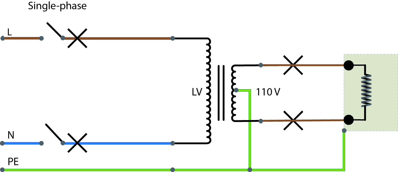
Figure 1 Typical arrangement of a low voltage (LV) supply and RLV system
Where are RLV systems used?
RLV systems are most commonly used on construction sites and in workshops. Section 704 of BS 7671:2018+A1:2020 details the requirements for construction sites, Regulation 704.410.3.10 (i) recognises RLV as a method of protection.
Regulation 704.410.3.10 (ii) of BS 7671:2018+A1:2020 permits the use of RCDs as a method of protection for a circuit supplying a socket-outlet with a rated current up to 32 A on a construction site. However, the usual approach is to use RLV systems.
Reasons for this include the fact that RLV systems have an impeccable safety record with no fatalities ever recorded, compared with RCDs and the requirement to frequently test them, the associated cost and their susceptibility to damage when installed in a harsh environment. If an RCD fails, a dangerous situation could occur. Transformers are proven to be reliable and have been proven to last for many years without maintenance.
What are the requirements of BS 7671:2018+A1:2020 for RLV systems?
Regulation 411.8 of BS 7671:2018+A1:2020 provides the requirements for RLV systems. The requirements for basic protection in Regulation 411.8.2 include basic insulation and barriers or enclosures, the same as for LV systems.
The requirements for fault protection are provided in Regulation 411.8.3. This can be achieved either with an overcurrent protective device, providing a disconnection time of five seconds can be met, or, if this can’t be achieved, by an RCD.
What type of protection is required for RLV circuits?
In theory, under fault conditions, the touch voltage may not exceed 30 V, which would put it in the extra-low voltage (ELV) range, which does not require disconnection. However, disconnection is required to comply with BS 7671:2018+A1:2020 and prevent unwanted thermal effects.
RLV circuits are no different to any other electrical circuit, in that suitable protection must be provided. This includes short-circuit and overcurrent protection, automatic disconnection, consideration of current-carrying capacity and voltage drop, which can be one of the major limiting factors, due to the reduced voltage and increased current, leading to an increase in the required conductor size.
As both conductors are line conductors, at a voltage above earth, all line conductors must be disconnected in the event of a fault. Therefore, a double-pole protective device must be used for single-phase circuits and a triple-pole device for three-phase circuits. It’s important to remember that all protective devices must be suitable for use with 110 V – manufacturers can provide guidance on this.
How do I calculate Ipf and Zs values for RLV systems?
It may be necessary to calculate the prospective fault current on the secondary side of the transformer. For this, the formula below can be used:
Ipf = 55 V
Zs
How do I measure earth fault loop impedance (Zs) on RLV circuits?
Some earth fault loop impedance testers provide the functionality required to perform Zs tests directly. It’s important to remember that there is not a neutral conductor on an RLV circuit, but two line conductors and therefore two R1 + R2, earth fault loop impedance (Zs) and prospective fault current (Ipf) tests will be required, one for each conductor, with the highest value being recorded on the certificate or report.
Unfortunately, not all test equipment has this functionality. However, an alternate method of determining Zs is by calculation. Note that the Zs measurement on an RLV circuit will be as far as the RLV transformer, i.e. the secondary winding only; the circuit supplying the RLV transformer will not form part of the earth fault loop impedance measurement.
Can I calculate earth fault loop impedance (Zs) on RLV circuits?
If required, the earth fault loop impedance can also be calculated using the formula below. For simplicity, this can be broken down into three steps.
Zs = Zp * (Vs/Vp)2 + Zpu (Vs)2/VA + (R1 + R2) Ω
Where:
Zp = the impedance of the primary supply circuit
Zs = the equivalent secondary impedance
Vp = primary voltage
Vs = secondary voltage
Zpu = the impedance of the transformer
VA = the volt-amp rating of the transformer
R1 and R2 = the final circuit line and protective conductor resistance
Step 1: the supply circuit (Zp)
First, we need the impedance of the line to neutral of the primary circuit, including the external earth fault loop impedance (Ze): this is called Zp. This value could be used in the complete calculation or it could be converted to a value that can be put into the transformer secondary (this is called a reflected value because it is being reflected from the primary to the secondary side).
Assuming the Ze is 0.2 Ω and the circuit supplying the transformer has a line to neutral impedance that is 0.3 Ω, the impedance of the supply at the primary terminals of the transformer is 0.5 Ω. Next, the reflected impedance must be calculated.
Zp x (Vs/Vp) 2
0.5 x (110/240) 2
0.5 x 0.21 = 0.11 Ω
Zp = 0.11 Ω (impedance of the supply reflected to the secondary side)
Note that Vs/Vp is the same as N2/N1 (where N is the number of turns on the transformer windings), so you should generally use 110/240 (not 230).
Step 2: the impedance of the transformer (Zpu)
Assuming the transformer is rated at 10 kVA, the details of the transformer are known, and the impedance is expressed as a percentage, for this example, 4 %, then:
Zpu x Vs2/VA
0.04 x 1102/10,000
0.04 x 12,100/10,000
0.04 x 1.21 = 0.05 Ω
Zpu = 0.05 Ω (transformer impedance)
Step 3: the impedance of the final circuit (R1 + R2)
For this example, the value of R1 + R2 is given as 0.03 Ω.
R1 + R2 = 0.03 Ω (the resistance value of the secondary circuit).
Zs at load = 0.11 Ω + 0.05 Ω + 0.03 Ω = 0.19 Ω
What are the maximum Zs values for RLV systems?
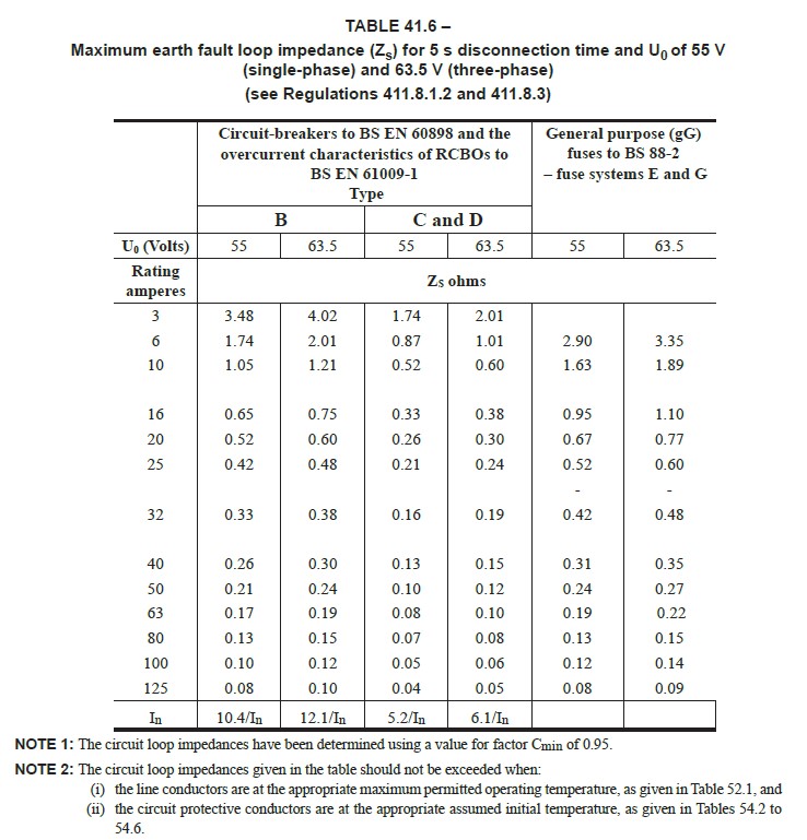
Table 41.6 of BS 7671:2018+A1:2020 provides maximum earth fault loop impedance values for BS EN 60898 and general-purpose BS 88-2 fuse systems. In practice, it is very difficult to achieve the values in Table 41.6. RLV systems are most commonly used on construction sites, where TT earthing systems are used. These generally have higher earth fault loop impedance, unless specialist earthing systems are designed and installed. This can sometimes be difficult to achieve when using smaller transformers, as they typically have a higher impedance. This can result in the maximum Zs value being exceeded at the transformer terminals before taking the circuit resistance into account.
It is for this reason that most RLV circuits are protected with a residual-current circuit-breaker (RCCB) or residual-current circuit-breaker with overcurrent protection (RCBO). However, it’s important to remember that these must be the correct type and suitable for the voltage range in order to work correctly on RLV systems, or the test button will not work. Most RCBOs that are designed to operate on a 230 V supply are likely to have single-pole thermal and magnetic protection that would be unsuitable for an RLV system.
Figure 2 Table 41.6 of BS 7671:2018+A1:2020: Maximum earth fault loop impedance values
Are RLV systems expensive to install?
The additional cost for an RLV system is the transformer. However, this cost can quickly be recovered when you consider that using RCDs for protection could be expensive, due to the need to prevent inconvenience or danger in the event of a fault, as identified in Regulation 314.1 of BS 7671:2018+A1:2020. For example, to prevent the whole site from losing power in the event of a single fault, multiple RCDs and circuits would be required, with time-delayed RCDs installed at source (and of course, the correct type of RCD would be important). More information on different RCD types can be found in the Which RCD Type? article from Issue 77 of Wiring Matters.
How do I identify the conductors for an RLV system?
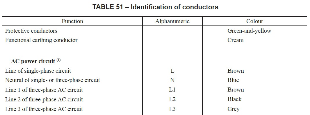
It’s important to remember that a single-phase RLV circuit does not have a neutral conductor, as there is not an earthed live conductor on the secondary side; however, the centre point of the secondary winding is earthed and the potential between each live conductor and earth is the same, i.e. 55 V. As shown in Figure 3, both line conductors on a single-phase RLV system should be identified by the colour brown or the letter ‘L’. Regulation 514.3.1 of BS 7671:2018+A1:2020 states that:
Except where identification is not required by Regulation 514.6, cores of cables shall be identified by:
(i) colour as required by Regulation 514.4 and/or
(ii) letters and/or numbers as required by Regulation 514.5.
Figure 3 Table 51 of BS 7671:2018+A1:2020: Identification of conductors
Summary
If, for functional reasons, the use of ELV is impracticable, then in the absence of any requirement for separated extra-low voltage (SELV) or protective extra-low voltage (PELV), RLV systems are a good alternative.
RLV systems are renowned to be a safe system for use in areas with increased risk of electric shock, such as construction sites. They offer increased protection from electric shock, due to the lower touch voltages when compared with an LV system, with the additional protective measure of ADS.
RLV systems are usually installed on construction sites, where the earthing arrangement is likely to be TT. Achieving ADS without the use of RCCBs/RCBOs is difficult, especially with smaller transformers and long cable runs. Due to the reduced voltage compared with a 230 V circuit, the voltage drop will be greater for an RLV circuit: this can limit circuit length and/or increase cable size.
Additional sources of information
BS 7671:2018+A1:2020 The 18th Edition of the IET Wiring Regulations Requirements for Electrical Installations
BS 7375:2010 Code of Practice for distribution of electricity on construction and demolition sites
BS 4363:1998+A1:2013 Specification for distribution assemblies for reduced low voltage electricity supplies for construction and building sites