MythBusters #6
True or false? All generators need to be earthed unless floating
Being a mythbuster column, this statement is, of course, untrue – not least because the term ‘floating’ is technically undefined, so is a meaningless expression. The earthing of generator sets has long been a source of confusion, particularly with smaller units like those used to power mobile units, such as catering vans or offices on construction sites.
The issue is not just with the way in which generator sets are used however, it is not uncommon for manufacturers’ instructions to be confused on the subject too. It is not unusual to see in generator operator manuals a requirement that the generator frame must be connected to an earth electrode, when in practice (given the way the alternator is configured), doing so will provide absolutely no benefit or electrical protection whatsoever.
It is often said that a generator must be ‘referenced’ to Earth. This again is a myth – in typical low voltage generators the mass of Earth plays no part in the electrical performance of the alternator (or inverter), and a generating set will still output 230 V, whether the frame or winding(s) is connected to Earth or not. But Earth can be, and is, used for fault protection with low-voltage generator based installations.
The history
Most guidance in the area of generator earthing stems from BS 7430 Code of Practice for protective earthing of electrical installations. This document has been updated many times in recent years and provides useful advice on designing earth electrode networks, the earthing of low and high voltage installations, and more. However, the sections covering generators were for a long time based on two rather historic principles – namely, that generators under 10 kVA typically didn’t need earthing, and that those over 10 kVA did. Most guidance published to date has been based on these two options.
Putting it into perspective, it is just as possible to get an injurious electric shock from a 2 kVA generator as it is from a 12 kVA one. It is unclear what the original engineering rationale was for the different power levels; it is probably a legacy of early generating set topologies when alternator configurations were quite simple and uniform.
The situation today
Much has changed over the years; alternators and their wiring configurations now come in a variety of configurations, including switchable single- or three-phase, star or delta, 110 V and 230 V dual outputs, self-exciting regulation and automatic regulation – and we are also now seeing inverter-based generators, designed to handle modern loads without issue. This is because the ubiquitous switched-mode power supply (SMPS), found in everything from PCs to LED lights, typically have power factors (PFs) near to unity. However, the PFs of the supplies tend to be slightly capacitive (leading) rather than inductive (lagging) and this causes instability in alternators, usually resulting in the generator shutting down or hunting.
A generator can work with quite inductive loads (they just burn more fuel, hence power factor correction (PFC) is popular), but if the PF swings the other way and becomes even mildly capacitive, generators struggle considerably, as the leading current causes (in broad terms) the alternator to accelerate. This explains the growing popularity of the inverter topology (Figure 1); this design will operate with a wide range of leading or lagging PF loads.
The topology in Figure 1 can confuse many, as the earth is ‘centre-tapped’ about the supply rails. This gives 115 V between line and earth and 230 V between lines. Most multifunction test instruments will see this as a fault and refuse to function; if you join earth and ‘neutral’ together to create a traditional set-up, then the output devices will fail catastrophically.
Figure 1 Inverter generator topology
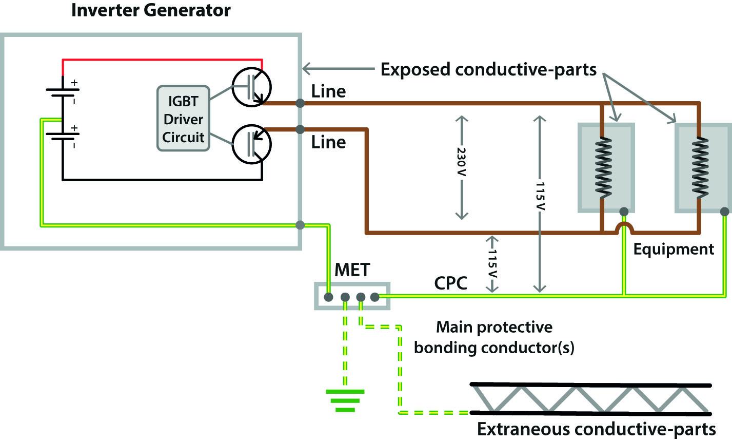
Some alternators are wired in a similar fashion, with the protective earth centre-tapped to the winding – in much the same way as the Reduced Low Voltage (RLV) system is designed, but with twice the operating voltage. Again, trying to connect a line and earth together will result in a shorted winding and potentially a big bill. The arrangement in Figure 1 is actually TN-S (if the earth electrode is deployed) and can be treated as such.
And the answer to the earthing question is….?
It all depends on the way the generator output is wired. It’s worth also at this point reminding ourselves of what role the mass of Earth plays in electrical safety in this low-voltage context. Consider a simple circuit such as that in Figure 2.
Figure 2 Simple circuit showing the fault path
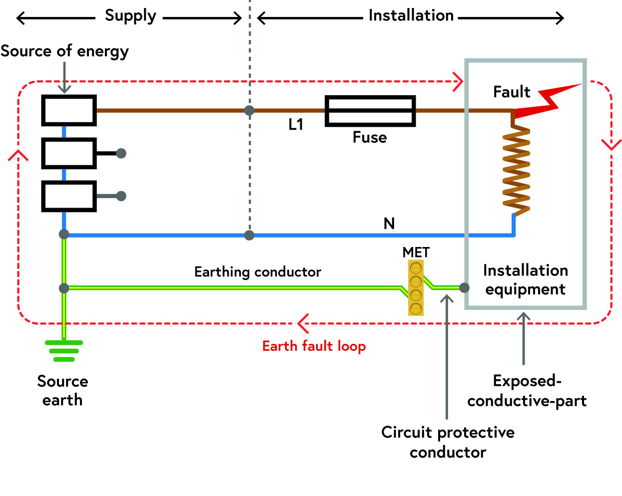
When the fault occurs in the equipment, current flows from the phase winding at the source, through the fuse, the casing of the equipment and back down the circuit protective conductor (CPC) to the neutral, before returning to the transformer. No current flows anywhere near the mass of Earth and even if the electrodes in Figure 2 were removed, the fuse should still operate in the event of the fault.
However, if the supply cable is damaged and a line conductor makes contact with Earth, current will flow through the mass of Earth, through the earth electrodes and back to the transformer winding. This will hopefully operate the protective device protecting the cable itself.
The key underlying theme is therefore that the mass of Earth is used for fault detection, typically for the failure of the insulation of cables. But what if you don’t use Earth for that purpose? With a generator that is not electrically connected with the mass of Earth, Earth itself plays no part and is not part of the electrical system. This is typified in the age-old problem of what to do with generators parked on a hard-standing where it is not possible to put down an earth electrode. Do you do nothing? Is it safe? Should you dig up the pavement and put one in?
Generator earthing arrangements
There are three typical topologies to consider. Figure 3 shows a generator set configuration that is fairly common and could be described as a ‘normal’ arrangement.
Figure 3 Standard earthed generator topology
In most respects, this is similar to an ordinary electrical supply, with the supply connected to Earth and a separate neutral and protective conductor provided – i.e. TN-S. As a result of the earth electrode being used at the generator, a common mistake on certificates is to see this arrangement described as TT, which it isn’t. The earth electrode at the generator in Figure 3 represents the first ‘T’ in TN-S, and not the second ‘T’ in TT.
Figure 4 shows the same topology, but without the earth electrode. This is one of the generator configurations that is addressed in the IET Practitioner’s Guide to Temporary Power Systems and is defined in the guidance as a ‘floating’ system. The protective conductor still functions to protect equipment, but Earth plays no part in this. As noted, ‘floating’ is an undefined term in any standard and is often used to describe the arrangement in Figure 4 as well as that in Figure 5. The IET Guide defines Figure 4 as a floating system as it operates as a TN-S arrangement, but the protective conductor is floating from Earth and hence is better described as IN-S rather than TN-S, because of the lack of earth electrode. The protective conductor arrangement in Figure 5 is not used for fault clearance in the same way.
Figure 4 'Floating' generator configuration
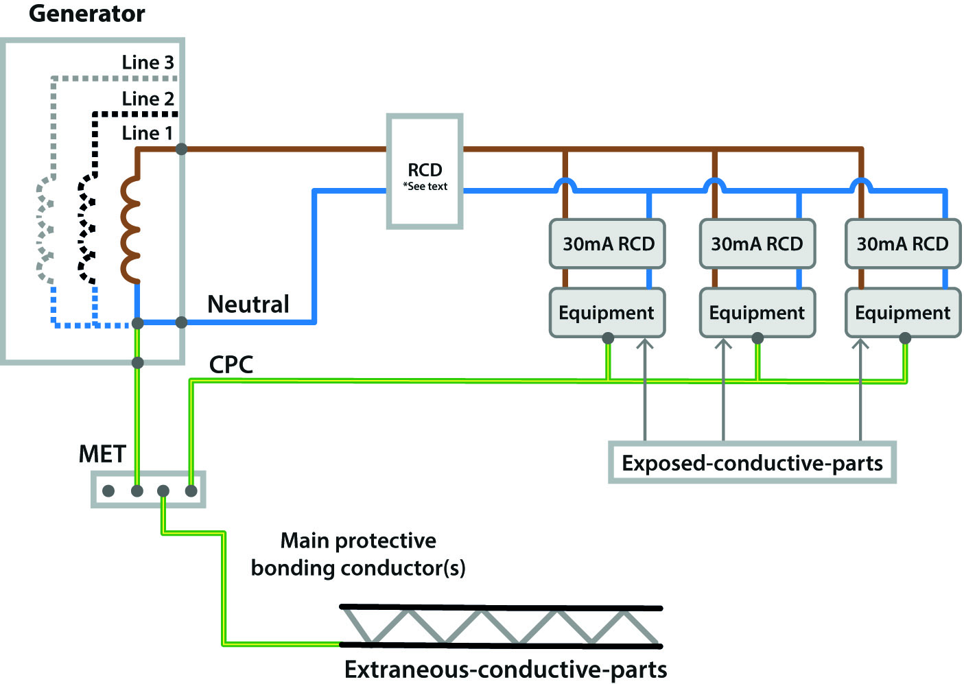
Technically, this topology is a departure from Regulation 411.4.1 of BS 7671:2018+A1:2020, which requires a “reliable and effective connection of the PEN or PE conductors to Earth”. However, as illustrated earlier, the connection with Earth may not be required, such as for a generator onboard a mobile unit or a generator supplying a site office via a short length of protected cable. It is a topology also used in installations deploying simple separation, such as for supplies to mobile units depicted in Figure 717.6 of BS 7671:2018+A1:2020. Figure 717.1 also describes a generator-based installation on board a mobile unit, as shown in Figure 4 above.
Such an arrangement is safe if contained within a unit such as those described in Part 7 of BS 7671:2018+A1:2020. It can also be safe for temporary systems in construction and similar, but with provisos. The main one is the use of a residual current device (RCD) on the output of the generator to provide protection against accidental earthing of the system (for example, the frame of the generator sitting in wet mud) or failure of cable insulation.
The RCD must be set at no more than 100 mA with a time delay of no more than 0.2 seconds; this affords a degree of selectivity with downstream devices (i.e. 30 mA devices on final circuits).
The other requirement of this floating mode is that it is for a short duration. It’s a control measure for when there is no other option. If possible, such systems should have an earth electrode; the protection will then be much more reliable, especially in detecting cable faults.
It is also important to think of the temporary distribution connected to the generator when considering the RCD rating. A generator supplying power tools or other final circuits directly would need to have a 30 mA RCD fitted on the output.
If the generator is supplying a distribution unit that has 30 mA RCDs protecting final circuits (such as those fitted in a consumer unit in a portable building), then the supply from the generator is a distribution circuit, not a final circuit, and can be treated as such when considering Regulation 411.3.3 of BS 7671:2018+A1:2020 (see also Note 1 of the same).
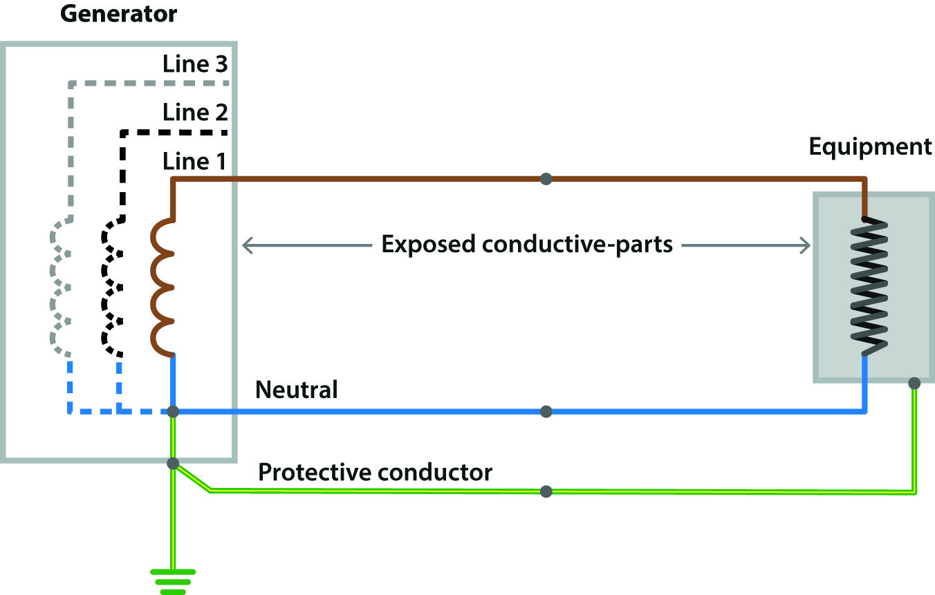
The third topology shown in Figure 5 is common with (but not limited to) smaller generating sets of 1 or 2 KVA. The keen-eyed reader will notice that this earthing arrangement is the same as the protective measure electrical separation, so Regulation Group 413 of BS 7671:2018+A1:2020 applies.
Figure 5 Generator configured as electrical separation
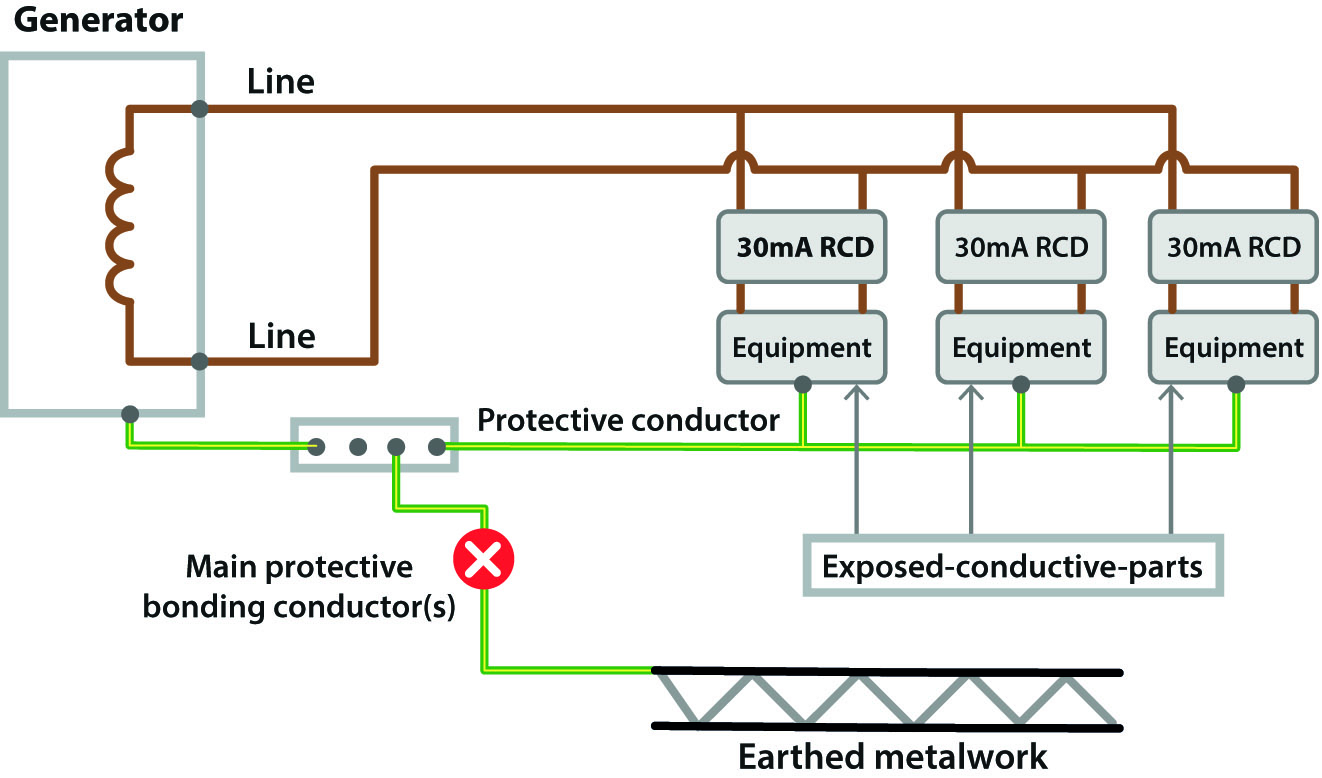
A notable feature about this arrangement is that an RCD on the output of the generator will serve no purpose – it is the only generator arrangement where this is so. In addition, equipment requiring a connection with earth for functional reasons (for example, for internal filtering or electromagnetic compatibility (EMC) measures, common on many modern power supplies) will not work effectively, as the protective conductor is not connected to the supply. This can lead to a voltage appearing on the casing of the equipment.
It is also important to ensure that the protective conductor is not connected to the mass of Earth (such as by connecting it to earthed metalwork), as this would turn the arrangement into an IT system (Regulation 411.6 of BS 7671:2018+A1:2020), which has differing requirements for protection, such as insulation monitoring devices (IMDs), for example. In practice, IT systems are difficult to implement as there is a requirement for a reliable earth electrode of known resistance to enable IMDs to function, which is often impractical to achieve for most temporary systems deployed for a short duration.
One aspect of the arrangement in Figure 5 is that a first fault will go undetected with Class I equipment. A fault with one item will cause the protective conductor to rise to (or near) the line voltage. In itself, this is not a problem, as there is no risk of shock, but a second fault on another item of equipment or a distribution cable could present a shock risk. For this reason, each item of Class I equipment must be protected by its own RCD complying with Regulation 415.1 of BS 7671:2018+A1:2020 (such as could be achieved by using socket-outlet RCDs). Regulation Group 418.3 of BS 7671:2018+A1:2020 should also be consulted if more than one item of Class I equipment is used.
In the event of a second fault, one of the RCDs will operate, thereby going back to the first fault condition and hence mitigating the risk. With Class II equipment, a fault does not give rise to the risk of shock and so any number of Class II items of equipment can be connected to the generator.
There is plenty of other related advice on this subject in the IET Practitioner’s Guide, including advice on cable and RCD selection for such systems, paralleling generator sets (or other supplies), example set-ups and more. It’s all new information and is worth being aware of if you deal with any form of temporary power generation. The new guide is available from the IET bookshop.
Section 551 of BS 7671:2018+A1:2020 also has salient advice on this subject, although it should be noted that this is currently being reviewed at an international level. Chapter 55 of BS 7671:2018+A1:2020 is quite detailed in describing alternative supplies and temporary generators. The principles of earthing are largely the same, whether the source is a rotating alternator or an electronic inverter, so this article will hopefully prove useful if you work with such systems.
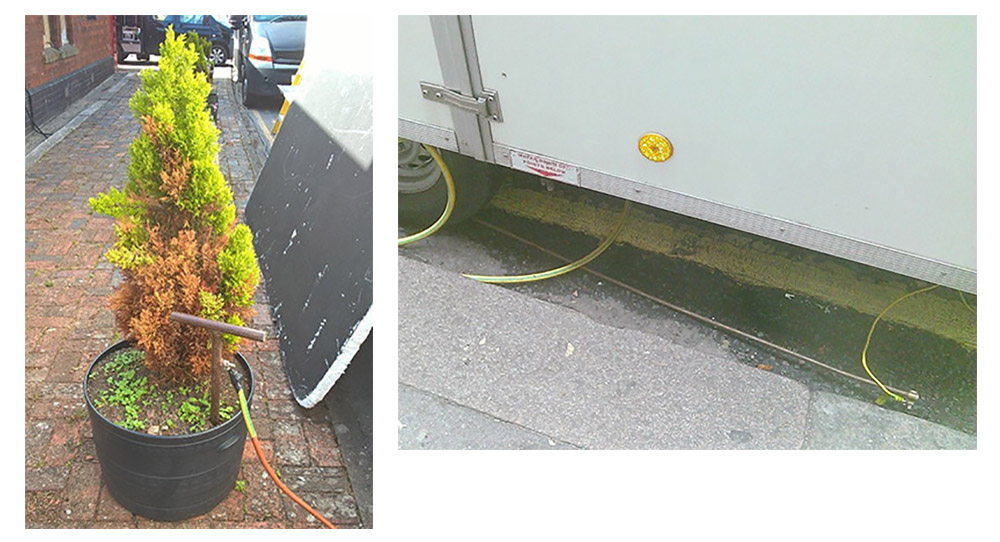
Finally, note that if you do deploy an earth electrode, it has to be effective. That means that its resistance must be low enough to cause sufficient current to trip the protective device on the output of the generator in the event of a fault to the mass of Earth. This will usually require very low values of earth electrode resistance, which in practice will be hard to achieve; hence RCDs on the output of TN generator topologies can provide much more effective protection. The electrodes in the pictures below will serve no practical purpose for electrical safety….