
History of insulation resistance testing
Insulation resistance testing, or ‘megger’ testing as it is more commonly known, does what it says on the tin: it tests the resistance of the insulation of all live parts in electrical circuits. The measured value is then compared with minimum values stated in the Standard, in order to verify that there is not a breakdown of insulation caused by damage to cables and other component parts of a circuit.
The 1st Edition of the IEE Wiring Regulations in 1882 required testing to be carried out, but it did not provide minimum values of insulation resistance. However, it did recognise the importance of testing an installation and stated:
The difficulties that beset the electrical engineer are chiefly internal and invisible, and they can only be effectually guarded against by "testing" or probing with electric currents. They depend chiefly on leakage, undue resistance in the conductor, and bad joints, which lead to waste of energy and the production of heat. These defects can only be detected by measuring, by means of special apparatus, the currents that are either ordinarily or for the purpose of testing, passed through the circuit.
The 2nd Edition of the IEE Wiring Regulations in 1888 did not provide any further detail in terms of the tests required or the minimum values of insulation resistance to be achieved, but Regulation no. 37 stated that “records should be kept of all tests, so that any gradual deterioration of the system may be detected”. This was the first requirement in the Wiring Regulations for a schedule of test results to be provided.
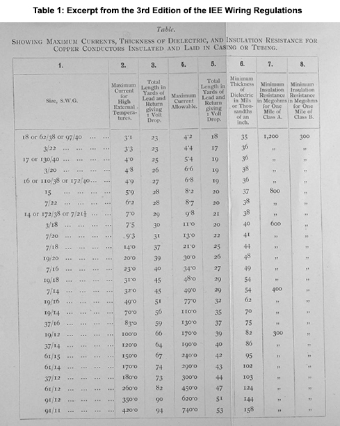
It wasn’t until the 3rd Edition of the IEE Wiring Regulations in 1897 that specific details for insulation resistance testing appeared. It was stated, in Regulation no. 15, that:
EMF equal to twice the EMF which will ordinarily be used is to be applied, and the insulation resistance between the whole system and earth must be measured after one minute’s electrification. The insulation should not be less than 10 megohms, divided by the maximum number of amperes required for the lamps and other appliances.
A similar test was also required to be carried out 15 days after the installation was put into service. At this time, the main concern of the Regulations was fire, as opposed to electric shock. It is unclear where this value came from originally; it is likely to have been something that was agreed amongst committee members.
Table 1 (below) is taken from the 3rd Edition and shows different minimum values of insulation resistance according to cable size and length.
By the time of the 4th Edition of the IEE Wiring Regulations in 1903, the requirements had changed. Regulation no. 78 stated that “the insulation resistance to earth must not be less in megohms than 30 divided by the number of points under test.” At this time, points were considered to be a “number of pairs of terminal wires from which it is proposed to take the current, either directly, or by flexibles, to lamps or other appliances”. This edition described an alternate method of testing with the installation complete: a reduced minimum value of 25 megohms divided by the number of 30 watt lamps. Connected equipment such as motors, heaters and other electrical appliances were required to have a minimum insulation resistance value of “500,000 ohms”. (Note that the value was in ohms, as opposed to megohms.)
The 5th Edition of the IEE Wiring Regulations introduced a new minimum value of insulation resistance for any individual sub-circuit. It stated that the value must not fall below 1 megohm, as for connected equipment.
It wasn’t until the 9th Edition of the IEE Wiring Regulations in 1927 that the requirements for insulation resistance testing became more detailed and differentiated between lighting, heating and power circuits. Interestingly, this edition stated that “heating and power circuits, with or without lighting points, may be tested if desired.” Testing of lighting circuits, however, was a requirement, as it was stated that these “shall” be tested. The Regulation for minimum insulation resistance value for equipment connected to the installation was amended to state that it “shall not be less than that specified in the appropriate British Standard Specification or, where there is no such specification, shall not be less than half a megohm”. The requirement for the minimum value of insulation resistance for the whole installation remained at 1 megohm.
The 13th Edition of the IEE Wiring Regulations in 1955 acknowledged the need to test circuits separately if required, and stated that “any reading less than 0.5 megohm shall be disregarded and the wiring under test shall be subdivided until a reading higher than 0.5 megohm is obtained.”
When the 16th Edition of the IEE Wiring Regulations was published in 1991, a table was introduced defining minimum values of insulation resistance, and test voltages were provided according to the nominal voltage of the circuit. The minimum value of insulation resistance for a distribution circuit or a switchboard up to and including 500 volts was 0.5 megohms.
The first European Regulations, CENELEC Part 6 Harmonized Document (HD), were published in 2006. At this point, agreements were in place obliging the committee responsible for BS 7671, JPEL/64, to adopt the technical intent of the HD. The 17th Edition, BS 7671:2008, was published shortly afterwards: the table from the 16th Edition was subsequently amended and the minimum value of insulation resistance was revised to 1 megohm – the value that is still used today.
Cables are manufactured to various standards, which detail minimum insulation resistance values for particular cable types at specific temperatures. However, these are the minimum values required to achieve compliance with the Standard – the actual values will be different and will vary between different manufacturers and according to the length of the cable.
The values identified in BS 7671:2018+A1:2020 are for distribution circuits and switchboards that are acceptable for the majority of installations. However, there may be special installations, such as lighting installations with cable runs several kilometres long, that may not comply with these values. In these situations, it would be appropriate to record this on the Electrical Installation Certificate (EIC) as an intended departure. The design values obtained using manufacturers’ data can be compared with the measured values, which will need to be adjusted according to temperature.
This information should be recorded on the EIC. It would assist in demonstrating that there is no lesser degree of safety than that required by Regulation 120.3 of BS 7671:2018+A1:2020. It could also prove useful when testing the installation in the future.
Summary
The minimum values of insulation resistance have changed over the years. There is no documented justification for the 1 megohm minimum value of insulation resistance, but it has survived the test of time and in practice has proved to be a useful starting point when determining the condition of the insulation of cables and electrical equipment.
There may be some special installations that do not meet this requirement. In these cases, the electrical designer must make an engineering judgement based on values obtained from the manufacturer and measurements taken on site. In such cases, it would be appropriate to record this as an intended departure, provided the resulting degree of safety is not less than that obtained by compliance with BS:7671:2018+A1:2020, as stated in Regulation 120.3.