
Changes to RCD testing in BS 7671:2018+A2:2022
The early style Residual Current Devices (RCDs) were highly effective protective devices but they have proven to be less reliable in modern buildings as a consequence of DC leakage and DC fault currents caused by electronic equipment. Subsequently, new types of RCD have been developed.
This article focuses on the changes introduced in Amendment 2 to BS 7671:2018 in respect to testing of RCDs (RCCBs & RCBOs as they are more commonly known), it also addresses a number of common questions relating to RCD technology. For further information on the different RCD Types and the selection process, see IET Wiring Matters article (Issue 77 September 2019), ‘Which RCD Type?’.
Figure 1

Brief history of RCDs
As with most inventions, RCDs were developed by different people. Dr Gottfried Biegelmeier (1924-2007) was an Austrian Physicist who filed a patent for the first residual current circuit-breaker (RCCB) in 1957. When RCDs were first developed, little was known about the effects of electric shock in human beings and, of course, the devices needed to be proved to work. As a result, Dr Biegelmeier carried out many of his experiments on himself, the results of which went into IEC report #479 (as it was known) but has since become IEC 60479 effects of current on human beings and livestock. For further information see, GOTTFRIED BIEGELMEIER, an oral history conducted in 1996 by David Morton, IEEE History Center, Piscataway, NJ, USA.
What are the changes to the requirements for selection of RCD Types?
Before we look at testing RCDs, it is worth pointing out that the requirements for selection and erection of RCDs have been amended. Regulation 531.3.3 of BS 7671:2018+A2:2022 states that the appropriate RCD shall be selected according to the presence of DC components and AC frequencies. Further, Type AC RCDs shall only be used to serve fixed equipment, where it is known that the load current contains no DC components.
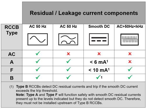
Type AC RCDs are affected by residual DC components and can become desensitized or ‘blinded’ and may not operate within the required time or, in some instances, may not operate at all. Table 1 summarizes the various types of RCD referred in BS 7671:2018+A2:2022 and their resilience to DC components.
Given the prevalence of electronic equipment in most installations, it is difficult to see how the electrical designer will be able to justify the use of Type AC RCDs. Many manufacturers have discontinued Type AC RCDs, preferring to supply type A as a minimum. Therefore, in future it is possible that Type AC RCDs will become obsolete due to lack of demand and Type A RCDs will become the common choice for most new installations, so it is important to understand the changes to the requirements for RCD testing.
For further information on the different RCD Types and the selection process, see IET Wiring Matters article (Issue 77 September 2019), ‘Which RCD Type?’
Table 1 Summary of RCD types
Why are changes to the requirements for RCD testing necessary?
Sub Committee A of JPEL/64 scrutinized the product standards for RCDs and noted the complexity of testing parameters, as well as the results permitted by the standards that could be used to prove the functionality of an RCD when bench tested in a laboratory.
It was noted that those testing RCDs in the field would find it difficult to carry out the variety of tests permitted and may not know which of the available tests would be applicable to a given make or type of RCD.
It was therefore agreed that the testing procedure could be greatly simplified and safety would remain unaffected since RCDs are, in any event, tested extensively by manufacturers prior to sale.
What are the changes to the requirements for RCD testing?
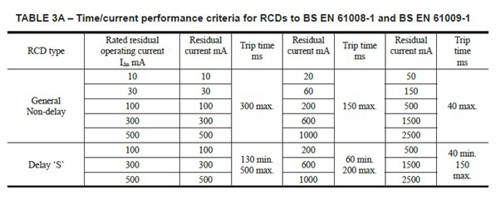
The good news is that the changes do not require you to purchase a new test instrument. In BS 7671:2018 the time/current performance criteria for RCDs to BS EN 61008-1 and BS EN 61009-1 were included in Table 3A of Appendix 3 as shown in Table 2. This has been deleted by BS 7671:2018+A2:2022.
Table 2 Table 3A from BS 7671:2018 - DELETED BY Amendment 2
The requirements for RCD testing in BS 7671:2018+A2:2022 are given in the notes to Regulation 643.7.1 for fault protection and Regulation 643.8 for additional protection. A note in each section states the requirements and the key points are highlighted below.
Regardless of RCD type, e.g. AC, A, F or B, an alternating current test shall be used at the rated residual operating current (IΔn), with a maximum operating time not exceeding 300 ms for general non-delay type RCDs.
For ‘S’ Type time-delayed RCDs, the operating time shall be between 130 ms (minimum) and 500 ms (maximum). S Type time-delayed RCDs are not applicable for additional protection, hence, the operating times are not included in Regulation 643.8.
There is no longer a requirement to perform a test using a test current equal to or higher than five times the rated residual current.
What is an alternating current test?
The type of test is selected on the instrument according to the RCD type. When the instrument setting selected is for an AC Type RCD, the test current applied is a 50 Hz alternating current. However, when the instrument setting selected is an A Type RCD, a pulsed direct current (DC) is superimposed on the 50 Hz AC waveform.
Whilst some testers are capable of testing different types of RCD with a variety of fault currents, BS 7671:2018+A2:2022 only requires an AC test to show compliance. This means that the test instrument needs to be set to the Type AC RCD setting regardless of RCD Type.
Each manufacturer’s instrument is different but changing the RCD Type is usually selected by pressing the relevant ‘function’ button on the instrument and the RCD Type symbol will change accordingly: see Figure 2. Most instruments will include a function to test general non-delayed and S Type time-delayed Type AC and Type A RCDs, some test instruments may also include a facility for testing other Types such as Type B RCDs.
Figure 2 Example, test instrument display screen

What is the maximum disconnection time for TT earthing systems using an RCD for fault protection?
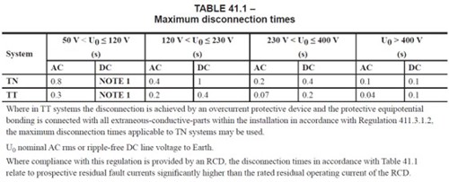
Given that an RCD may take up to 0.3 seconds (300 ms) to disconnect it would appear at first glance that some disconnection times in Table 41.1 may not be achievable, for example, the maximum disconnection time for some final circuits on a TT earthing system is 0.2 seconds (200 ms), as shown in Table 3. However, a note under the table indicates that earth faults are of negligible impedance and it follows that disconnection times would be commensurately higher since a value of, for example, a residual current of 60 mA would be expected to provide a disconnection time of 150 ms and 40 ms (0.04 seconds) for a residual current of 150 mA, as shown in Table 2. Therefore, an operating time of 300 ms would be considered acceptable for a TT earthing system.
Table 3 Table 41.1 BS 7671:2018+A2:2022
Can other types of RCD testing be carried out?
Some will argue that in order to verify if an RCD will operate correctly in the presence of DC components, using the appropriate DC test instrument setting for the RCD Type must be carried out in addition to testing using the AC type setting.
Generally, an RCD either works or it doesn’t and, in essence, the test is to prove that the RCD is functional and is not intended to confirm that it still performs as per the relevant product standards and manufacturers requirements. RCD testing required by product standards is carried out by the manufacturer and is called type testing.
Whilst BS 7671:2018+A2:2022 doesn’t require other types of RCD testing, however additional tests are not precluded and may be useful for fault finding purposes, these tests could include:
- ½ x IΔn test
- 5 x IΔn test
- RCD type (AC, A, B, F)
- RCD tripping current (ramp test)
- Phase angle (0° & 180°)
However, if you do choose to carry out additional testing, it is important to understand how the instrument operates when using different test settings for the various RCD types. It is also important to understand what results to expect according to product standard requirements.
Further information on RCD operating and non-operating times can be found in the relevant product standards. Type A and Type AC RCCBs and RCBOs are manufactured to BS EN 61008 and BS EN 61009 respectively, whereas Type F and Type B RCCBs and RCBOs are manufactured to BS EN 62423.
RCD testers are designed and manufactured to BS EN 61557-6 Effectiveness of residual current devices (RCD) in TT, TN and IT systems for testing electrical installations. The standard requires that the instrument be able to verify correct disconnection of the supply in the event of a fault but it does not provide requirements for extensive product standard testing. Subsequently, not all instruments will be well suited to carrying out anything more than the most rudimentary of tests.
What are the different characteristics of the Type A setting on the test instrument?
Figure 3

Now that we have strayed away from using AC tests, things start to get more complicated and further knowledge both of the limitations and configuration of the instrument you are using and relevant product standards is needed, in order to verify the results.
When the Type A setting is selected on the instrument, a half wave pulsating residual test current superimposed on a smooth direct current of 6 mA is produced, which effectively applies a 1.4 multiplier to the rated residual current (IΔn). For example, if the 30 mA setting is selected, the RCD will be subjected to a test current of 42 mA (30 x 1.4 = 42 mA).
Similarly, for instruments with a setting for Type B RCDs a multiplier of two times IΔn is applied as required by the product standard, BS EN 62423:2012 Type F and type B residual current operated circuit-breakers with and without integral overcurrent protection for household and similar uses.
This is where knowledge of relevant product standards is essential, it would be reasonable to expect a 40 ms maximum disconnection time for a test at five times IΔn as would be the case with an AC test. However, this is not the case as the product standard BS EN 61008 requires a half wave pulsating residual current of 0.35 A (350 mA), see Table 4 extracted from BS EN 61008-1:2012+A2:23-1:2012+A11:2015.
If the Type A RCD setting is selected on the test instrument, the test current is increased by a factor of 1.4. Therefore, if the instrument is set to perform a test on a 30 mA RCD at five times IΔn, a test current of 210 mA (30 x 5 x 1.4 = 210 mA) would be produced which may not be sufficient to operate the RCD within the required time as the product standard requires a test current of 350 mA (0.35 A), as described previously.
Some test instruments have a variable trip current setting, if a tripping current of 50 mA at five times IΔn was selected on the Type A setting, a trip current of 350 mA could be simulated (50 x 5 x 1.4 = 350 mA). However, the variable test current feature is not available on all test instruments.
Table 4 Maximum values of break time for Type A RCD extracted from BS EN 61008-1:2012+A2:23-1:2012+A11:2015

What is the expected endurance of an RCD?
All mechanical or electrical equipment has a finite lifespan. For RCDs, part of the product standard test procedure is to ensure a minimum number of operating cycles. BS EN 61008 requires RCDs having IΔn > 10 mA are subjected to 2000 operating cycles, each operating cycle consisting of a closing operation followed by an opening operation. This is a combination of manual operation, using the test button and using a test current of IΔn.
For those that decide to continue to carry out all of the tests previously required, it is important to consider what the benefits really are and if the lifespan of the RCD be reduced, possibly to the point where it may not work when required.
RCD testing issues
Many of the issues encountered when testing RCDs are down to user error as opposed to faulty RCDs. It may come as a surprise to some, but RCD testing should be carried out at the RCD with the outgoing wiring disconnected. However, this is not usually done. The usual live working procedures must be considered, and suitable precautions taken when carrying out work near live parts.
RCD tests may be affected by loads downstream that contain electronic equipment or may incorporate permanent leakage current due to the capacitance of cables where circuit lengths are considerable.
An RCD test instrument operates by applying a fault current and recording how long it takes the RCD to disconnect the supply. Where circuits comprise capacitance due to connected loads or due to long cable lengths, even after the RCD has operated, the capacitance in the circuit will continue to discharge influencing the result recorded by the instrument.
Further information on RCD testing can be found in IET Guidance Note 3 Inspection and Testing and PD IEC TR 62350:2006 Guidance for the correct use of residual current-operated protective devices (RCDs) for household and similar use which states that ‘The testing current should be applied between the upstream and downstream terminal of the RCD’, see Figure 4 extracted from IET Guidance Note 3 Inspection and Testing.
Figure 4 RCD testing arrangements taken from IET Guidance Note 3 Inspection & Testing

Cascaded RCDs for selectivity
In addition, cascaded RCDs are sometimes provided to meet selectivity requirements. A common example is RCDs with residual current rating not exceeding 30 mA in a caravan, required by Regulation 721.415.1 of BS 7671, supplied by a socket-outlet or pitch-outlet, which itself is required to be protected by an RCD with residual current rating not exceeding 30 mA by either Regulation 411.3.3 or 708.415.1 of BS 7671:2018+A2:2022. When the downstream RCD is tested, the upstream RCD may operate; there are methods available to address this when testing. For further information, see IET Guidance Note 3 Inspection and Testing.
Summary
The days of selecting an RCD according to current rating and rated residual current alone are gone, now the designer must select the RCD according to the nature of the residual fault currents, including pulsed or steady-state DC components expected to be present.
The requirements for testing RCDs have been simplified, a single test is all that is required to show compliance with the minimum requirement laid out in BS 7671:2018+A2:2022. Regardless of RCD type, the test is carried out using an alternating test current, applied at the RCD’s rated residual operating current IΔn, the maximum disconnection time is expected to be less than 300ms for a general non-delay type RCD. For S type time-delayed RCDs, the operating time should be 130 - 500 ms. Other kinds of RCD testing may be useful for fault finding purposes.
It is important to note that a test at both 0 and 180 degrees is not required.
It is essential to understand the limitations of the test instrument and product standard requirements when testing RCDs using the available RCD Type settings on the test instrument.
If you think you may have a faulty RCD, firstly ensure there are no factors within the installation that are influencing the results. Always carry out RCD testing in accordance with industry guidance and manufacturer’s instructions.
Finally, remember an RCD has a finite lifespan, so, give consideration to whether or not extensive testing is beneficial or may have the opposite effect.
Further reading
IET Wiring Matters article, ‘Which RCD Type?’
Eaton RCD application guide [PDF, 12.8MB]
IET Guidance Note 3 Inspection and testing
BS 7671:2018+A2:2022 Requirements for Electrical Installations, IET Wiring Regulations, 18th Edition.
PD IEC/TR 62350:2006 Guidance for the correct use of residual current-operated protective devices (RCDs) for household and similar use.
BS EN 61008-1:2012+A12:2017 Residual current operated circuit-breakers without integral overcurrent protection for household and similar uses (RCCBs). General rules.
BS EN 61009-1:2012+A13:2021 Residual current operated circuit-breakers with integral overcurrent protection for household and similar uses (RCBOs). General rules.
BS EN 62423:2012+A11:2021 Type F and type B residual current operated circuit-breakers with and without integral overcurrent protection for household and similar uses.
BS EN IEC 61557-6:2021 Electrical safety in low voltage distribution systems up to 1 000 V a.c. and 1 500 V d.c. Equipment for testing, measuring or monitoring of protective measures. Effectiveness of residual current devices (RCD) in TT, TN and IT system.
IEC 60479 series Effects of current on human beings and livestock
Acknowledgments
I would like to express my great appreciation to the following individuals for their valuable contributions to this article.
- BEAMA
- Connor Flynn
- Gary Gundry
- Graham Kenyon
- Jit Patel
- Jon Elliot
- John Peckham
- Leon Markwell
- Mark Coles
- Mark Hadley
- Paul Skyrme
- Peter Monfort
- Richard Giddings
- Richard Wardak
- Steven Devine