
Mythbuster #12 – A galvanizing tale of separation and isolation
As in many areas of life, electrical work is not without its colloquialisms. You’ll often hear about earth bonding, commando sockets or choc block*, for example.
While none of these are correct terms (there’s no such thing as an earth bond, commando is a manufacturer’s brand name for IEC 60309 connectors and choc block has no clear origin as a connector type), the general meanings are well understood by electricians when discussing the topics concerned.
However, there is an area of electrical design work where the colloquialisms can be misleading to the point that using the wrong language might (and has) ended up with the wrong system being specified.
The concepts of electrical separation, isolation, galvanic separation and simple separation all share some common characteristics, but all are very different in respect of safety or functional application. For example, it is common to hear of people specifying an ‘isolation transformer’ whereas all that is required is simple separation.
When explaining the differences, a good place to start is Regulation Group 410 of BS 7671:2018+A2:2022+A3:2024. Chapter 41 is concerned with protection against electric shock as applied to an electrical installation.
Regulation Group 410 provides some commentary on the origins of the requirements of the principles to be applied (contained in another standard, BS EN 61140), namely, that hazardous-live-parts should not be accessible and that accessible parts should not become hazardous-live in both normal and fault conditions.
It goes on to say “According to 4.2 of BS EN 61140, protection under normal conditions is provided by basic protective provisions and protection under single fault conditions is provided by fault protective provisions.”
The protective provisions most commonly deployed are basic insulation (basic protection) and automatic disconnection of supply (fault protection), but there are other fault protection measures such as extra-low voltage, electrical separation and double insulation, for example.
This is where the differences begin to appear. Electrical separation is the only one in the list that is not just a functional tool in the designer’s armoury – it is a protective measure.
Electrical separation
This will be familiar territory for many electricians as it is the protective provision found in a shaver socket, for example.
Regulation Group 413 details the actual requirements but the salient aspect is that it utilizes insulation of live parts as the basic protective measure in common with other provisions, however, the fault protection does not rely on automatic disconnection but is “provided by simple separation of the separated circuit from other circuits and from Earth.” Figure 1 illustrates the concept.
Figure 1 Example of electrical separation for one item of current using equipment (Regulation 413.1.2). (Image taken from the IET Guide to Temporary Electrical Systems, 2nd Edition, Figure 5.19.).
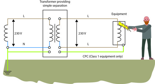
With this, protection from the risk of electric shock is provided by the lack of connection of the secondary side of the transformer with the general mass of Earth and other electrical circuits. If a user is simultaneously in contact with the mass of Earth and a faulty item of equipment, as shown in Figure 1, no electric shock to Earth will occur as there is no path for current to flow back to the secondary winding.
The second key part is in Regulation 413.3.2 which requires that “The separated circuit shall be supplied through a source with at least simple separation, and the voltage of the separated circuit shall not exceed 500 V.” What is not required, despite popular thought, is the use of an isolating transformer.
Isolation and simple separation
The difference between the two is one of insulation. In essence, a transformer providing isolation has an increase in insulation robustness between the primary and secondary.
Some transformers (such as toroidal types) have the primary and secondary windings wound over each other on the former, and the lacquer on the wires forms the insulation between them. This can fail (for example, through overheating) and as a result, primary voltage can appear on the secondary side, leading to a risk to the user.
Isolation transformers are required in certain applications where this could be an issue. An example is a separated extra-low voltage source (SELV), such as that required for an extra-low voltage lighting installation (Part 715). Here, the transformer must be a safety isolating transformer complying with BS EN 61558-2-6.
Such a transformer is illustrated in Figure 2. Note that a transformer providing isolation is depicted with more vertical bars between the primary and secondary, compared to a single line as shown in the transformer in Figure 1.
Figure 2 Safety isolating transformer providing separated extra-low voltage. Note 1 on the diagram states that the transformer should comply with BS EN 61558-2-6 or BS EN 61558-2-8. Image taken from IET Guidance Note 5: Protection Against Electric Shock, Figure 7.2.).

The transformer concept is usually illustrated in electrical books (as in Figure 2) as using traditional wire-wound transformers, though many modern switched-mode power supply designs achieve the separation or isolation electronically.
Simple separation as a tool
This is a form of separation commonly used for practical reasons, such as to reduce the risk of earth loops or to protect users from the touch voltages arising from a PEN failure in a TN-C-S supply.
With this method, there is no electrical connection between the supply and the separated circuit. This is illustrated in Figure 3, where simple separation has been used to provide electrical separation between one electrical system and another.
Note that there is no electrical connection between primary and secondary and ‘simple separation’ is defined in BS 7671 Part 2 as “Separation between circuits or between a circuit and Earth by means of basic insulation.”
Figure 3 Example of simple separation on the supply to a mobile unit. (Image taken from BS 7671:2018+A2:2022+A3:2024, Figure 717.1.).
The advantage with this is that it is possible to recreate a different earthing arrangement in an installation. For example, a TN-C-S arrangement could be used to supply a transformer with a TN-S or IT output topology.
It also prevents leakage currents from equipment in the installation presenting on the primary supply and will limit some harmonic currents too.
It can also be used to break circulating currents (‘earth loops’) which can cause issues with signal or data circuits; there are many applications where simple separation can be advantageous.
Galvanic isolation
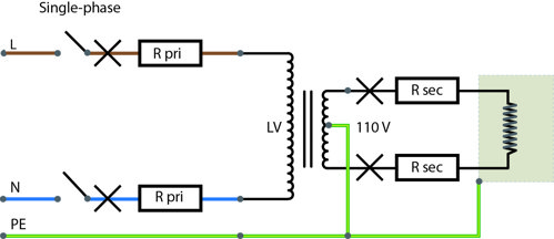
This has a subtlety of its own. Isolation as a technique may not necessarily require separation from Earth – examples include reduced low voltage (110 V) and PELV systems - where the transformer provides isolation, but the earthing arrangements are connected together on both primary and secondary sides.
Figure 4 shows an example of a reduced-low voltage isolating transformer which illustrates the concept.
Figure 4 Reduced low voltage system. (Image taken from IET Guidance Note 5: Protection Against Electric Shock, Figure 4.8.).
Where isolation between windings, along with separation from Earth (and other circuits), is required, galvanic separation may be necessary. In a transformer, capacitance between the windings can give rise to stray leakage currents between the two.
This can be an issue, particularly for vessels in a marina connected to the shore supply, for example. While separation from the shore supply is important for protection against faults in the distribution (which could make the boat reach a hazardous voltage), the leakage currents can give rise to galvanic currents circulating in the system.
Metal boat parts in water will corrode and this is usually countered by fixing a sacrificial anode, for example, a metal such as zinc which will erode and electrolytically protect metal parts such as rudders, shafts or propellers.
The capacitive effects in the supply transformer can allow circulating currents between the shore supply secondary connected to the boat and the primary through the hull, water and Earth.
For this reason, many transformers have a Faraday or ‘electrostatic’ shield providing galvanic isolation to limit the stray capacitive currents that could flow. Galvanic isolation is also required in some DC applications too, such as functional bonding in solar photovoltaic (PV) systems (Regulation 712.542.102).
Summary
This article gives an overview of the different methods of separating one circuit from another. It is important to make sure that the right type of separation and isolation is specified for the application and that equipment is selected to suit.