
Boat wiring - why BS 7671 doesn’t address all the issues…
Introduction
Whilst BS 7671 sets the scene, this article aims to identify those elements of boat electrical wiring systems that require a different approach - particularly from the traditional ‘selection and erection’ perspective. In the small craft world, these differences highlight the need for more focussed installation practices that are driven by the presence of vibration, movement of the craft due to the operating environment and sea states, external heat sources and of course, the presence of water.
The information provided in this article is presented in the form of wiring system design considerations sourced from the following standards/guides:
- BS EN ISO 13297:2020+A1:2002 Small craft – Electrical systems – Alternating and direct current installations.
(Applies to DC installations which operate at a nominal voltage not exceeding 50 V DC and single-phase AC installations which operate at a nominal voltage not exceeding 250 V AC.) - IEC 60092-507:2015 – Electrical installations in ships.
(Captures ISO 13297 and AC three-phase systems not exceeding 500 V AC.) - BS EN ISO 16315:2016 – Small craft – Electrical propulsion system.
- IET On-Board Guide: Electrical Safety in Small Craft.
To underpin the necessary design considerations, examples of best practice are also included.
Wiring system design principles
Electrical system designers should first seek to understand the small craft’s layout, construction and intended use, together with the anticipated operational environment and any operational hazards and risks. This activity should include:
- Identifying load characteristics for all items of DC and AC equipment to be installed. For each equipment type, manufacturer’s data should be obtained, including full load current and equipment terminal voltage limits for correct operation under load, and also under transient conditions created by the operation of autonomous power sources.
- Designing the distribution systems from power sources for the DC and AC systems by scheduling each final circuit for both DC and AC installations.
- For DC circuits, establishing:
- Continuous service and maximum currents required in each circuit (Ib), and minimum equipment terminal voltage requirements.
- The length of each cable route and any associated cable environment issues (Cx) when selecting cable cross-sectional areas (csa) and insulation temperature rating of each cable.
- The voltage drop in each circuit and checking that minimum equipment terminal voltage under full load conditions is maintained under design minimum battery terminal voltage conditions. (Typically, 90 % nominal voltage.)
- For AC circuits, establishing:
- Continuous service and maximum currents required in each circuit (Ib), and minimum equipment terminal voltage requirements.
- The length of each cable route and any associated cable environment issues (Cx) when selecting cable csa and insulation temperature rating of each cable.
- The (R1 + R2) for each circuit from its associated circuit protective device.
NOTE : The Ze component of the overall earth fault loop impedance from the TN-S shore transformer to a 16 A rated shore-supply socket outlet on-board a craft is likely to be both variable (depending on the location of a craft in a marina or similar location) and indeterminate (except by direct measurement in a particular craft location). The Ze component must therefore be assumed to be less than Zs = 2.73 Ω (where: Zs = Ze + (R1 + R2)shore) up to the shore-supply socket-outlet.
- Establishing each final circuit sheath/insulation type of each DC and AC cable relative to calculated maximum current to be carried and conductor csa considering:
- The ambient temperatures and any sections of cable routes passing through insulating material.
- When cables passing through compartments may be covered/carried in conduits and enclosures.
- Cables being potentially bunched/in contact with other cables particularly with different maximum insulation temperature limits (for example, thermoplastic, thermosetting).
Sizing of conductor csa
The approach adopted by the IET’s On-Board Guide is similar to that adopted in BS 7671. Overcurrent protective devices provide both fault current and overload current protection. The design current (Ib) of the circuit must first be established and the overcurrent device rating (In) is then selected so that In is greater than or equal to Ib. The tabulated current-carrying capacity of the selected cable (It) is then given by the following formula for simultaneously occurring factors C:
![]()
The various rating factors are identified as follows:
- Ca for ambient temperature which may increase the current carrying capacity for conductors under 45 °C or reduce if greater (see Table 10.2 in the IET’s On-Board Guide).
- Cg for grouping.
The following multiplying factors (Cg) are to be applied to the tabulated Table 13.2 of the IET’s On-Board Guide when considering single multicore cables:
- 85 for two-core cables.
- 70 for three- and four-core cables.
Where bunching of a number of circuits or cables together is required, Table 10.4 of the IET’s On-Board Guide provides Cg multiplying factors for increasing groups of cables individually or multicore.
Ci for thermal insulation
For a single cable likely to be totally surrounded by thermally insulating material over a length of more than 0.5 m, the current-carrying capacity should be taken (in the absence of more precise information) as 0.5 times the current-carrying capacity for that cable installed in ventilated conditions.
Where a cable is totally surrounded by thermal insulation for less than 0.5 m, the current‑carrying capacity of the cable should be reduced appropriately depending on the size of cable, the length in insulation and the thermal properties of the insulation. The derating factors in Table 10.3 of the IET’s On-Board Guide are appropriate to conductor sizes up to 10 mm2 in thermal insulation with a thermal conductivity λ greater than 0.04 Wm-1K-1.
NOTE: Lighting cables are frequently installed behind insulated deckhead cladding, but, where LED type luminaires are fitted, then cables may not need to be derated due to low service currents.
The Cf for the type of protective device and for most installations using circuit-breakers or totally enclosed fuses on-board small craft will be 1.0.
Estimation of voltage drop in pairs of live conductors and value of (R1 + R2) for AC circuits
The terminal voltage measured at an item of equipment under its full load conditions is determined by:
- The voltage drop in the complete circuit between source and equipment.
- The terminal voltage of the source, for example, battery/DC generator for DC systems, on-board generator or shore-supply for AC which may reduce/droop under varying load conditions.
Typical resistance per metre run of single core cable with tinned annealed stranded copper conductors at 20 °C can be found at Table 13.3 of the IET’s On-Board Guide.
To calculate the voltage drop in the pair of conductors supplying an item of equipment in millivolts (mV), the resistance per metre (mΩ/m) of the particular conductor csa (see Table 13.5 in the IET’s On-Board Guide) is multiplied by the design current of the circuit Ib and the length of run in metres L:
Volt drop (mV) = resistance per metre (mΩ/m) × Ib × L
Value of (R1 + R2) for AC circuits
For the purpose of estimating (R1 + R2) in circuits up to 16 mm2 csa, the resistance value (R1 + R2) will be the same as used for the circuit volt drop since the cross-sectional area of the circuit protective conductor will be the same as for the live conductors as required in marine practice. However, where there are cables or circuits with live conductors greater than 16 mm2 nominal conductor size, the csa of the circuit protective conductor (cpc) may be reduced and the value of (R1 + R2) will correspondingly vary as shown in Table 13.4 of the IET’s On-Board Guide.
Correction factors for resistance values of pairs of conductors or (R1 + R2) temperature at times of test (ambient) or conductor service temperature
The resistance per metre values (mΩ) tabulated at a temperature of 20 °C (R0) in Table 13.5 of the IET’s On-Board Guide should be adjusted as required by multiplication by the following factors to estimate resistance per metre (R) for various anticipated conductor temperatures in accordance with the following equation:
R = R0 [1 + 0.00373 (t – 20)]
For convenience, Table 13.5 in the IET’s On-Board Guide provides calculated multipliers for correcting resistance values (mΩ) for ambient or service temperatures.
Conductor identification (DC systems)
DC negative conductors should be identified by black or yellow insulation (see Figure 2). Where craft are equipped with both DC and AC electrical systems, the AC system uses black insulation for live conductors.
Figure 2 DC switch/panel-board wiring
Means of identification other than insulation colour may be used to identify DC positive conductors if properly identified on the craft’s electrical system wiring diagram(s).
Where craft are equipped with both DC and AC electrical systems, insulation coloured brown, white or light blue should not be used in the DC system (unless such conductors are clearly separated from any AC conductors and are specifically identified as DC).
All equipotential bonding conductors should be identified by insulation coloured green, or green with a yellow stripe. Alternatively, such conductors may be in the form of uninsulated strip or braid. Conductors with green or green/yellow insulation must not be used as current-carrying conductors.
NOTE: A coloured stripe may be added to conductor insulation for identification purposes.
Conductor identification (AC systems)
Black or brown coloured insulation should be used for the active (phase) conductor of single-phase AC electrical systems.
Neutral conductors of single-phase AC electrical systems are to have insulation coloured white or light blue.
All protective conductors are to be identified by insulation coloured green, or green with a yellow stripe.
Separation of AC and DC systems
DC circuit conductors should not be contained in the same wiring system as AC circuit conductors unless one of the following methods of separation is used:
- Housed within separate conduit, trunking or sheathing.
- Fixed directly to a surface and separated by at least 100 mm.
- Insulated for their system voltage and installed in a separate compartment of a conduit or trunking system.
- For multi-core cables/cords, the cores of the DC circuit(s) need to be separated from the cores of the AC circuit(s) by a grounded/earthed metal screen of equivalent current-carrying capacity to that of the largest csa core in either circuit.
Cable termination
All conductors should have suitable terminals fitted. To eliminate vibration-induced fretting of individual conductor strands, there are to be no terminations in the form of bare wires to any screw or stud type terminal (see Figure 3).
Figure 3 No suitable terminal fitted
Solderless crimp-on terminals/lugs are to be attached by a crimping tool that is compatible with the terminal/lug size and type.
Tensile (pull-off) testing
To ensure that all conductor-to-connector and conductor-to-terminal connections are adequately made, they need to be subjected to a tensile force of at least the values detailed in Table 1 below.
Table 1 Tensile (pull-off) force
| csa | Tensile force | csa | Tensile force | csa | Tensile force | |||
| mm2 | N | kgf | mm2 | N | kgf | mm2 | N | fgk |
| 0.75 | 40 | 4 | 6 | 200 | 20.4 | 50 | 400 | 40.8 |
| 1 | 60 | 6.1 | 10 | 220 | 22.4 | 70 | 440 | 44.9 |
| 1.5 | 130 | 13.3 | 16 | 260 | 26.5 | 95 | 550 | 56.1 |
| 2.5 | 150 | 15.3 | 25 | 310 | 31.6 | 120 | 660 | 67.3 |
| 4 | 170 | 17.3 | 35 | 350 | 35.7 | 150 | 770 | 78.5 |
NOTE: Where multiple conductors of differing csa are terminated in a single connector/terminal, the smaller csa conductor has to withstand the applied tensile force without separating from the connector/terminal.
Protection of exposed terminal shanks
With the exception of circuit protective conductors and bonding conductors (see Figure 4), the shanks of all exposed terminals/lugs need to be protected from short-circuit hazards by the use of insulation barriers or sleeves (see Figure 5).
Figure 4 Compliant bonding conductor exposed terminal lug shank
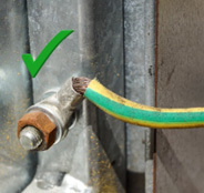
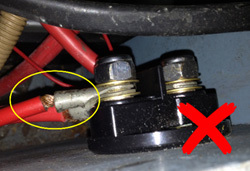
Figure 5 Non-compliant exposed terminal lug shank on a +12 V connection to a battery isolation switch
Terminal blocks (and associated terminations)
To avoid vibration induced failures, ferrule bootlace crimps (see Figure 6) must be used with screw type terminal blocks. This will reduce individual strands separating from the connection.
Figure 6 Ferrule terminal
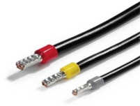
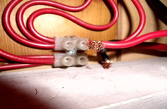
Figure 7 Effect of vibration-induced fretting
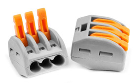
Alternatives to the ubiquitous ‘choc-block’ come in the form of the screw-clamp (see Figure 8) or the increasingly popular, lever-arm locking-type screwless terminal block (see Figure 9). These devices compliantly accommodate bare conductor strands because the mechanical action of their conductor clamping devices ensure physical retention and electrical contact without damaging the conductor strands.
Figure 8 Screw clamp terminal block
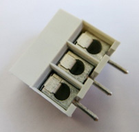
Figure 9 Screwless lever arm locking terminal block
When considering a simple screw or nut terminal block of the types illustrated in Figures 10 and 11, many would assume that simple ring or spade terminals could be used in conjunction with these types of terminal blocks and, for the domestic environment, they may well be correct.
Figure 10 Terminal block (screw fixings)
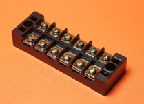
Figure 11 Terminal block (nut fixings)
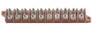
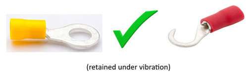
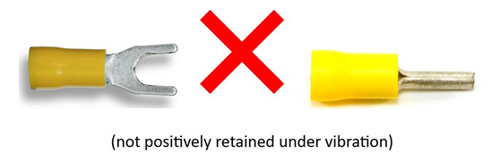
However, due to the presence of vibration on small craft, ISO 13297 mandates that all terminals/lugs shall be of the ring or captive hook type because they are not dependent on screw/nut tightness alone for their retention (see Figure 12).
Figure 12 Suitable for terminal blocks with screw/nut fixings
When used with the type of terminal blocks illustrated in Figures 10 and 11, open-ended spade or ‘pin’ type terminals/lugs (see Figure 13) are unsuitable for such use as they are not positively retained under vibration conditions.
Figure 13 Unsuitable for terminal blocks with screw/nut fixings
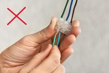
Twist-on ‘wire nut’ connectors (see Figure 14) are also prohibited due to their ability to loosen when subjected to vibration.
Figure 14 Unsuitable for in-line conductor joining
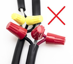
Figure 15 Inadequate battery cable retention
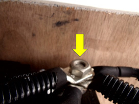
Where multiple connections are made to stud terminals (for example, battery terminals), the number of connections should not exceed four. This requirement is driven by two factors. Firstly, terminals/lugs by their very shape prohibit axial alignment which in turn results in radial dispersion around the securing stud; secondly, and driven by the vibration element, there is a need to ensure that the long-understood engineering ‘rule of thumb’ that requires a minimum of 2.5 thread studs to be visible beyond the upper face of the securing nut is implemented.
It should also be noted that a terminal stud needs to accommodate not only the terminals themselves, but room is also needed for placement of locking devices such as locking/spring washers. Figure 15 is an example where 4 thick-section battery terminal lugs are precariously secured by nothing more than a plain nut. Note, not only the absence of any locking device but also the fact that only 50 % of the plain nut threads are actually engaged! (See Figure 15 arrowed.)
Termination and fixings - material requirements
While terminal studs, securing nuts and associated washers need to be corrosion‑resistant (for obvious reasons), it is important to remember that these items also need to be galvanically compatible with each other as well as the conductor and associated terminal material. Un-plated steel and aluminium should not be used for terminal stud securing nuts or washers.
NOTE: The practice of solder-tinning stranded conductors is effectively prohibited as such action creates a solid conductor which is then susceptible to vibration‑induced fracture risk.
Cable routing and support
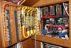
All small craft cable and conductors need to be supported throughout their length in conduits, trunking, cable trays or individually supported at a maximum of 450 mm intervals (unlike the standard of wiring found on a high percentage of UK inland craft (see Figure 16)).
Figure 16 Poor cable routing and support
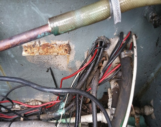
Conductors which may be susceptible to physical damage should be protected by trunking, conduit or other equivalent means. Note that several of the cables illustrated in Figure 16 pass through drilled holes in the steel bulkhead with no additional protection (for example, sleeving or a cable grommet).
Conductor connections need to be in locations protected from the effects of weather or contained within enclosures in accordance with IEC 60596:1989 and rated IP 55 minimum. All above-deck connections that are exposed to intermittent immersion are to be contained within enclosures in accordance with IEC 60596:1989 rated IP 67 minimum.
To avoid damage to insulation, all cables are to be routed away from engine exhaust systems and other on-board heat sources. Cables should be located no closer than 250 mm from dry exhaust systems and 50 mm from water-cooled exhausts.
Current-carrying conductors need to be located above areas where water can accumulate (for example, bilges) and at least 25 mm above the level at which any automatic bilge pump activates.
In circumstances where conductors need to be routed below the anticipated bilge water level, all wiring and associated terminations need to be located in enclosures in accordance with IEC 60596:1989 and rated IP 67 minimum. Connections below the foreseeable water level are not permitted.
If you wish to dig deeper into the vagaries of small craft wiring systems, visit the IET bookshop to order a copy of the IET’s On-Board Guide: Electrical Safety for Small Craft today!