
Isolation and switching for mechanical maintenance
During the debate, and to avoid the problem of heat-damaged isolators, the question was asked whether isolators for equipment such as showers and ovens could be omitted and is it acceptable to rely on isolation at the consumer unit? This article answers the debate by looking at the practicalities and requirements of BS 7671:2018+A2:2022 with respect to isolation and switching for mechanical maintenance.
1. What are the requirements for isolation?
BS 7671 is non-statutory but the Electricity at Work Regulations 1989 (EAWR) are written into law.
The EAWR are general in their application and refer throughout to 'danger' and 'injury'. Danger is defined as ‘risk of injury’ and ‘injury’ is defined in terms of certain classes of potential harm to persons. Injury is stated to mean death or injury to persons from:
- electric shock;
- electric burn;
- electrical explosion or arcing; or
- fire or explosion initiated by electrical energy.
Regulation 12(1)(b) of EAWR states ‘where necessary to prevent danger, suitable means shall be available for […] the isolation of any electrical equipment’, where ‘isolation’ means the disconnection and separation of the electrical equipment from every source in such a way that the disconnection and separation is secure.
2. What are the requirements of BS 7671:2018+A2:2022?
The main requirements for isolation and switching are provided in Chapter 46 and Section 537 of BS 7671:2018+A2:2022.
With respect to switching off for mechanical maintenance, the term isolation can be broadly split into three categories covering different parts of the installation:
- installation;
- circuits; and
- equipment.
2.1 Installations
Chapter 46 of BS 7671:2018+A2:2022 sets out the requirements for isolation and switching and Regulation 462.1 states that:
‘Each electrical installation shall have provisions for isolation from each supply.’
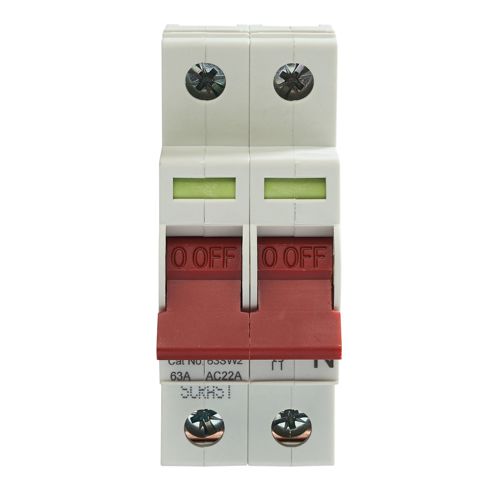
This is provided in the form of a main linked switch or linked circuit-breaker located as near as practicable to the origin of the installation as a means of switching the supply on load as set out in Regulation 462.1.201 of BS 7671:2018+A2:2022.
Figure 1 Main switch disconnector
2.2 Circuits
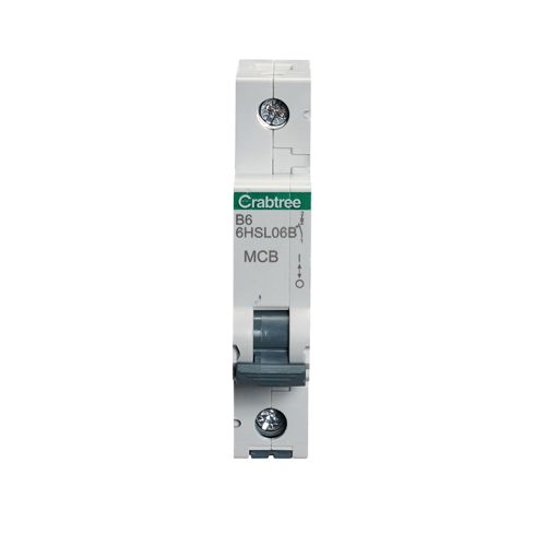
Regulation 462.2 of BS 7671:2018+A2:2022 requires every circuit to be provided with isolation for all live conductors, except those detailed in Regulation 461.2 of BS 7671:2018+A2:2022, which provides exceptions for TN-C-S and TN-S systems where the neutral or PEN conductor is reliably connected to Earth.
Figure 2 Circuit-breaker
2.3 Equipment
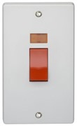
Devices for isolation and switching or plugs and socket-outlets can be used to provide isolation for equipment. Note that for plugs and socket-outlets, isolation is achieved by withdrawal of the plug from the socket-outlet. The switch of a socket-outlet is not required to be suitable for isolation, see ‘(6)' to Table 537.4 of BS 7671:2018+A2:2022. Where mechanical maintenance may involve a risk of physical injury, means for switching off shall be provided in accordance with Section 464 of BS 7671:2018+A2:2022.
Figure 3 50 A isolator switch for equipment
3. What are the requirements of BS 7671:2018+A2:2022 for switching off for mechanical maintenance?
Regulation 464.2 of BS 7671:2018+A2:2022 requires suitable means to prevent equipment from being inadvertently or unintentionally reactivated during mechanical maintenance, unless the means of switching off is continuously under the control of any person performing such maintenance. This is typically an isolation device designed to allow a padlock to be installed to ensure safe isolation and prevent inadvertent re-energization.
4. Which devices are suitable for isolation?
Table 537.4 of BS 7671:2018+A2:2022 provides guidance on protective, isolation and switching devices and their suitability for isolation, emergency switching off and functional switching. This includes a wide range of devices from circuit-breakers to contactors. Where protective devices are suitable and can be used for isolation of circuits, this is marked on the side of the device as shown in Figure 4.
Figure 4 Isolation symbol (see IEC 60617 identity number S00288)

IEC 60617 - Graphical Symbols for Diagrams
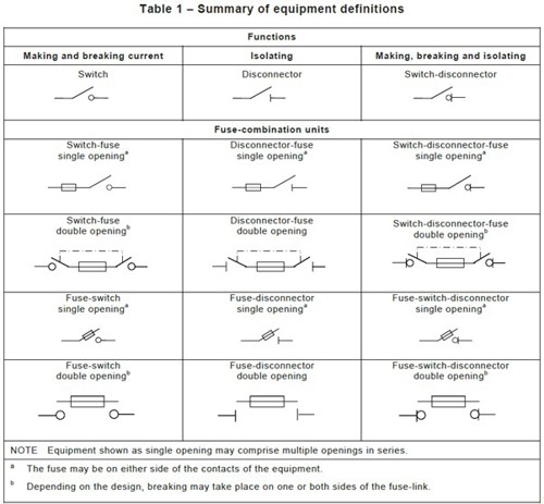
Table 1 of BS EN 60947-3:2015 provides a useful summary of the different types of equipment and definitions.
Figure 5 BS EN 60947-3:2015 Table 1 summary of equipment definitions
5. Where should an isolator be located?
The isolator needs to be installed so that it is clearly identified by position or labelling. Regulation 537.3.2.4 states that:
‘Devices for switching off for mechanical maintenance shall be clearly identified by position or durable marking so as to be identifiable for their intended use.’
‘Identified by position’ means, for example, if it can clearly be seen that the purpose of an isolator is for a particular piece of equipment. If it is decided to locate the isolator away from the equipment for a particular reason, it shall be clearly identified.
6. Is it acceptable to isolate at the consumer unit for mechanical maintenance?
There is nothing in BS 7671:2018+A2:2022 to prevent isolation at the consumer unit for mechanical maintenance. The installation can be isolated by operating the main switch, as it is required to be a double-pole device suitable for switching the supply on load and as a means of isolation, in accordance with Regulation 462.1.201. The installation could be considered to be under continuous control or locked off if required.
The main consideration is the type of equipment connected and what is required in the manufacturer’s instructions. Frequently switching a high current inductive load is likely to reduce the lifespan of the protective device, it’s important to remember that the primary function is a protective device.
Then there are the practicalities to consider. For example, isolation at the consumer unit in a dwelling to carry out a maintenance task to replace equipment which takes 15 minutes once every five years may be acceptable. Whereas the isolation of an office block or house of multiple occupancy to carry out maintenance work on a more frequent basis will be more inconvenient and probably not acceptable.
7. Can I use a protective device for isolation?
Isolating an individual circuit as opposed to the whole installation using the main switch is more desirable as there is less inconvenience when others are using the installation.
The requirements for isolation and switching in TT systems are different to that for TN systems. For a TN-S system, where the neutral conductor can be considered to be reliably at earth potential, the neutral need not be disconnected, therefore it is permissible use the protective device for isolation, see Regulation 531.2.2 of BS 7671:2018+A2:2022.
For TT systems, the neutral must be disconnected for isolation. This could be achieved by using double-pole protective devices, but it is important to note that most readily available devices are single-pole, therefore this method of isolation would not be suitable for TT installations.
Whilst it is acceptable to use a protective device for isolation, it should be remembered that where a protective device such as circuit-breakers, AFDDs, RCBOs and RCDs are used for isolation, the primary function of these devices is protection and as a consequence are not intended for frequent load switching.
Where a protective device is used for frequent duty, the number of operations and load characteristics according to the manufacturer’s instructions should be taken into account. This is stated in ‘(5)’ to Table 537.4 of BS 7671:2018+A2:2022.
8. What do manufacturer's instructions say?
Regulation 134.1.1 of BS 7671:2018+A2:2022 requires the installer to take account of manufacturer’s instructions. The advice provided in manufacturer’s instructions vary.
Looking at the manufacturer’s instructions for a 10.5 kW shower, the general safety section states that a suitable double-pole isolation switch for supply disconnection must be incorporated in the fixed circuit in accordance with current wiring rules. At this point it could be assumed that isolation at the consumer unit is acceptable but it’s important to read further.
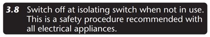
Item 3.8 of the electrical installation section on page three of the manufacturer’s instructions recommend switching off at isolating switch when not in use as shown below in Figure 6. Given the message that ‘this is a safety procedure recommended with all electrical appliances’, it is difficult to see how omitting a local isolator could be justified.
Figure 6 Manufacturer’s instructions for an electric shower
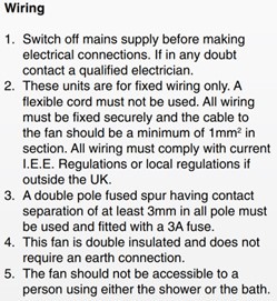
The example shown below in Figure 7 is of manufacturer’s instructions for an extractor fan. It states that a double-pole fused spur having contact separation of at least 3 mm in all poles must be used and fitted with a 3 A fuse.
Figure 7 Manufacturer’s instructions for an extractor fan
9. What do the product standards say?
The international standard for household and similar products is the IEC 60335 series. Clause 7.12.2 of IEC 60335-1:2020 Household and similar electrical appliances – Safety – Part 1: General requirements states:
7.12.2 If a stationary appliance is not fitted with a supply cord and a plug, or with other means for disconnection from the supply mains having a contact separation in all poles that provide full disconnection under overvoltage category III conditions, the instructions shall state that means for disconnection must be incorporated in the fixed wiring in accordance with the wiring rules.
Summary
Isolation at the consumer unit is permitted but it’s important to consider the practicalities and requirements of the manufacturer of the equipment.
Where single-pole protective devices are used, consideration for the type of earthing system is required. Where protective devices are used for isolation, it is important to take account of the manufacturer’s instructions with regards to the number of mechanical and electrical operations.
Manufacturers of electrical equipment often recommend the installation of device(s) for isolation and switching because turning off the equipment when not in use is a safety procedure recommended with all electrical appliances.
Further information on isolation and switching can be found in IET Guidance Note 2: Isolation & Switching.