
Determining the maximum earth fault loop impedance for protective devices to BS EN 60898 & BS EN 60947-2
1. Why determine and record the maximum permitted earth fault loop impedance for a protective device?
When selecting a device for fault protection, whilst utilizing the protective measure automatic disconnection of supply (ADS), it must be ensured that the device will disconnect in the required time, as stated in Regulation 411.3.2 of BS 7671:2018+A2:2022. This can be confirmed by ensuring the maximum measured earth fault loop impedance (Zs) is less than or equal to the maximum Zs permitted by the device. The maximum permitted Zs should be recorded on the Generic Schedule of Circuit Details from Appendix 6 of BS 7671:2018+A2:2022 when compiling forms for initial verification and periodic inspection and testing.
A circuit-breaker or a moulded case circuit-breaker (MCCB) that is manufactured to BS EN 60898 or BS EN 60947-2 respectively is commonly used to provide ADS as well as overload protection within an electrical installation and, whilst the focus of this article is on fault protection, Section 433 of BS 7671:2018+A2:2022 covers the requirements for protection against overload current.
2. What is the maximum disconnection time when employing automatic disconnection of supply as the protective measure?
Regulations within 411.3.2 of BS 7671:2018+A2:2022 set out the disconnection time requirements when utilizing ADS as the protective measure.
The required disconnection time is dependent on the following:
- the system voltage to earth (U0);
- the earthing arrangement;
- if the circuit is a distribution circuit or final circuit;
- the rated current of the circuit; and
- whether or not the circuit includes a socket-outlet.
The examples in Table 1 are based on a TN earthing arrangement, with a nominal voltage to earth of 230 V, and include their maximum disconnection time.
These examples cover the most common scenarios in a TN system, although to establish the required disconnection time for a circuit, including when a TT system is employed, see regulations within 411.3.2 of BS 7671:2018+A2:2022.
Table 1 TN earthing arrangement disconnection times
|
Example |
Arrangement |
Maximum disconnection time |
|
1 |
Final circuit up to 63 A, including a socket-outlet |
0.4 s |
|
2 |
Final circuit up to 32 A that serves fixed equipment only |
0.4 s |
|
3 |
Distribution circuit |
5 s |
|
4 |
Final circuit exceeding 32 A that does not serve a socket-outlet |
5 s |
3. Devices for fault protection
This article is based on utilizing devices manufactured to BS EN 60898 and BS EN 60947-2 to provide fault protection for ADS. It is worth mentioning that fault protection can be provided by an alternative device, the most common scenario for this is when using a residual current device (RCD) for fault protection purposes, this occurs mostly when a TT earthing system is utilized.
This article is based on using thermal magnetic devices to BS EN 60898 and BS EN 60947-2 for fault protection purposes, other devices are beyond its scope.
4. Selecting a device for fault protection
As mentioned in Section 1 of this article, the overload protective device is also usually utilized for fault protection purposes, therefore it is selected based on the characteristics of the circuit it is supplying. Section 433 of BS 7671:2018+A2:2022 PROTECTION AGAINST OVERLOAD CURRENT gives the requirements to be met in relation to overload protection.
Generally, the current rating of the device (In) is selected once the load of the circuit (Ib) has been determined and follows the general requirement In ≥ Ib.
Another consideration is the start-up current of the connected equipment. Circuit-breakers or MCCBs to BS EN 60898 or BS EN 60947-2 respectively have tripping curves B, C or D to allow for different levels of start-up current and it is worth noting that as the tripping curve increases alphabetically, the current required to operate the device instantaneously also increases. Due to this, it is advantageous to select the device with the lowest letter alphabetically that will permit the required start-up current requirements of the load.
Another requirement to be met when selecting the device is that it is rated for the possible fault current at its installation point. This requirement is set out in Regulation 434.5.1 of BS 7671:2018+A2:2022.
5. How to determine the maximum ZS of the selected device
Following the selection of a device from the previous section, the maximum permitted ZS must be obtained to ensure compliance with the disconnection time as stated in Regulation 411.3.2 of BS 7671:2018+A2:2022.
It is common practice in smaller installations to use Table 41.3 from BS 7671 to determine the maximum permissible Zs for a circuit-breaker to BS EN 60898, however Appendix 3 of BS 7671:2018+A2:2022 states:
“The maximum values of earth fault loop impedance to achieve the disconnection time vary with the different types of protective device and also between manufacturers. Wherever possible designers should use the manufacturer’s specific data.”
It goes on to say that wherever possible, designers should use the manufacturer’s specific data.
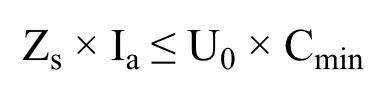
The values in Table 41.3 are obtained from the time/current graphs in Appendix 3. The formula from Regulation 411.4.4 of BS:7671:2018+A2:2022 states:
Formula 1 Extracted from Regulation 411.4.4 of BS 7671:2018+A2:2022
The characteristics of the protective devices […] and the circuit impedances shall fulfil the following requirement:
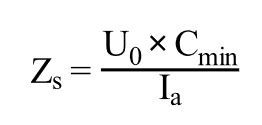
Transposing this formula to make ZS the subject matter gives the following:
Formula 2 Extracted from Appendix 3 of BS 7671:2018+A2:2022
Where:
Cmin is a correction factor to account for voltage variations. This is given as 0.95 in Appendix 3 of BS 7671:2018+A2:2022.
U0 is the nominal AC rms line voltage to Earth.
Ia is the current causing operation of the device in a specified time. This is obtained from manufacturers’ data and is covered in the next section.
5.1 How to obtain Ia from Appendix 3
To find the Ia of the selected protective device, the manufacturer’s time/current graphs are required. The values from Table 41.3 are based on the time/current values from Appendix 3 of BS 7671:2018+A2:2022.
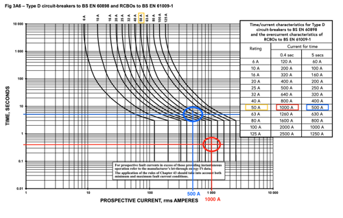
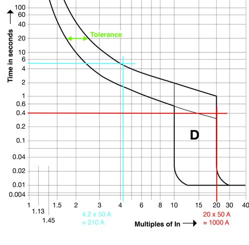
Figure 1 is extracted from BS 7671:2018+A2:2022 to illustrate how the values from Table 41.3 are obtained. This graph represents thermal magnetic circuit-breakers. The magnetic representation on the graph for the selected circuit-breaker is the vertical line that starts at 0.1 s and ends at 2 s, the thermal representation follows on from this, which starts at 2 s and is represented by a curve that concludes at the top of the graph where the size of the device is indicated.
With the correct graph selected, a horizontal line is drawn in relation to the disconnection time required, the red line on Figure 1 indicates a time of 0.4 s on the axis of the graph, the next step is to draw a second line vertically at the point in which the horizontal line intersects the time current/curve of the selected device. The vertical line will enable determination of the current required for operation from the axis.
The Ia for a 50 A device from the graph with a 0.4 s disconnection time in this case is 1,000 A. This intersects with the magnetic representation for the device.
A second example is indicated with a blue line on the graph. This again is for the 50 A device, although with a 5 s disconnection time, the Ia for a 50 A device in this case is 500 A. This intersects with the thermal representation for the device.
Figure 1 Type-D circuit-breakers to BS EN 60898 and RCBOs to BS EN 61009-1 (Figure 3A6 from Appendix 3 of BS 7671:2018+A2:2022)
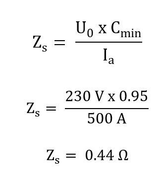
5.2 How to calculate Zs once Ia has been determined
With the value of Ia determined for a 50 A device’s 0.4 s and 5 s disconnection times, the maximum permitted Zs can now be obtained using Formula 2. This is carried out below:
(a) 0.4 s disconnection time:
(b) 5 s disconnection time:
When the calculated values are compared with the values from Table 41.3, they are identical.
5.3 How to obtain Ia from manufacturer’s data
Obtaining the Ia from a manufacturer’s graph is no different to what was carried out in the previous steps, although the graph may look a little different. One of the differences can be that the manufacturer has the tolerances of their device built into the time/current curves. When calculating the maximum Zs it should always be based on the worst-case scenarios. If the graphs have the tolerance included, the highest magnitude of current must be selected from the curve and due to the current and impedance being inversely related, this will give a lower maximum Zs to be met.
Some time/current curves do not have the tolerance built into them and in these instances the manufacturer will declare a tolerance, for example, ±20 %. If this tolerance is not included in the graph, it must be included in the maximum ZS calculation. An example of this based on a 20 % tolerance is indicated in Formula 3.
Formula 3 Maximum Zs formula with the tolerance of the device accounted for
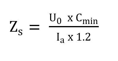
Figure 2 depicts how to obtain the maximum Zs from a specific protective device where the tolerance of the device is depicted on the time/current curve.
Figure 2 Time/current curve of a manufacturer’s device
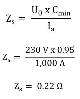
The values of Zs from Figure 2 have been calculated and are recorded below based on a 50 A protective device. This has been carried out for both the 0.4 s and 5 s disconnection times:
- 4 s = 0.22 Ω
- 5 s = 1.04 Ω
When the values above are compared with the values from BS 7671:2018+A2:2022, the 0.4 s disconnection time is identical, although when a 5 s disconnection time is permitted, the maximum permitted Zs is considerably higher. This can be advantageous when designing a circuit with a 5 s disconnection time.
6. How to obtain Ia when settings are present on an MCCB
While the examples given above are based on circuit-breakers, the principle for obtaining the Ia for a thermal magnetic MCCB is the same, however, there may be settings on the device to take account of.
Other than the most basic MCCBs, most will have a setting for adjusting the thermal setting characteristic of the device, and also have a setting present for the magnetic characteristics.
The basic settings are:
- Ir : adjusts the long-time current thermal setting; and
- Isd (or Im) : adjusts short-term magnetic setting.
The Ir adjustment is dependent on manufacturer, although this can be a factor of the In value, such as 0.8-1.0. As an example, an MCCB with an In rating of 160 A with an Ir setting of 0.8 would give an Ir of 128 A (160 A x 0.8 = 128 A).
Similarly, the Isd setting can be somewhere around 1.5 – 10, which is a factor based on the In or Ir setting of the device. As an example, using the Ir value obtained above and an Isd setting of 5, the Isd would be 640 A (128 A x 5 = 640 A).
Once the values above have been ascertained, the steps below will enable the establishment of the maximum Zs for the corresponding 0.4 s and 5 s disconnection times.
0.4 s disconnection time
For the 0.4 s disconnection time, it is not necessary to consult the graph as Isd equals Ia. Referring to the previous section, a factor may be required to account for the tolerance of the device. For the example below, a tolerance of 20 % is used, although the manufacturer’s data shall be consulted for this value.
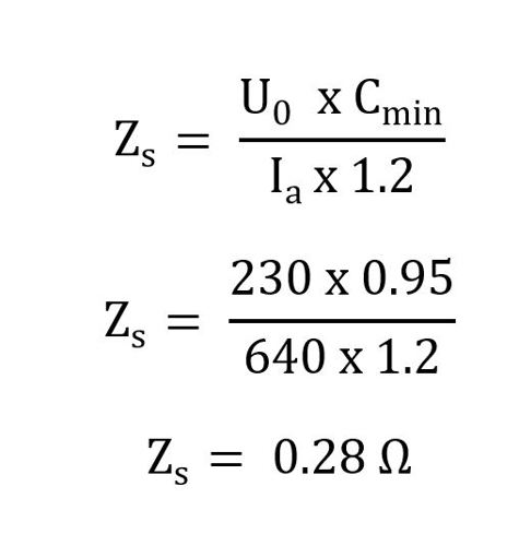
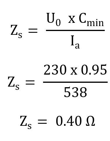
5 s disconnection time
To obtain the Ia for a 5 s disconnection time, the time/current graph would be referenced to obtain the Ia. Utilizing the graph in Figure 2, the values of current on the axis gives a multiple of In rather an actual current figure. If we did this as a multiple of Ir (128 A) we would get 4.2 x 128 = 538 A, where 4.2 is the multiple of Ir as obtained previously. With the current Ia obtained, the maximum permitted Zs can now be calculated as shown:
7. Correction factor due to temperature rise under load
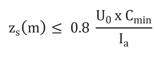
The method used in this article does not include a correction factor for the increase in resistance caused by the increase in temperature of the conductor under load. When designing a circuit, the temperature rise is built into the cable design calculation. When testing is carried out to obtain the measured value of Zs in accordance with Regulation 643.7.3 of BS 7671:2018+A2:2022, it is carried out at an ambient temperature. Due to the increase in resistance with the increase in temperature when the cable carries the circuit’s load, a factor is applied to the maximum permitted Zs for the circuit’s protective device. Formula 4 should be applied when comparing the maximum permitted Zs, with the Zs obtained from the testing procedure.
Formula 4 Extracted from Appendix 3 of BS 7671:2018+A2:2022
Where:
Zs(m) is the measured impedance of the earth fault current loop up to the most distant point of the relevant circuit from the origin of the installation (Ω).
0.8 is the factor to take into account the increase of resistance of the conductors with the increase of temperature due to the load current.
U0 is the nominal AC rms line voltage to Earth.
Ia is the current in amperes causing operation of the protective device within the time stated in Table 41.1 (of BS 7671:2018+A2:2022), or within 5 s according to the conditions stated in Regulation 411.3.2.3.
C(min) is the minimum voltage factor to take account of voltage variations depending on time and place, changing of transformer taps and other considerations.
8. Devices other than thermal magnetic devices
Although the focus of this article is limited to thermal magnetic devices, devices are available with electronic trip units. These are generally used to obtain selectivity between devices where this cannot be achieved by their thermal magnetic counterparts. When designing for selectivity, manufacturer’s/third-party design software makes comparison of the time/current curve simpler to ensure selectivity is achieved.
If the device’s maximum Zs is not obtainable, for example due to a third-party design, some manufacturers provide a formula for working out the maximum Zs, although this usually limited to a 0.4 s disconnection time.
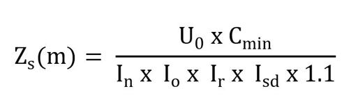
Formula 5 was derived from a Schneider technical data sheet based on the Compact NSX, with a micrologic 2.2 trip unit. This formula is informative only.
Formula 5 Maximum Zs formula derived from Schneider’s technical data sheet 002 Issue 3
Where:
Zs(m) is the measured impedance of the earth fault current loop up to the most distant point of the relevant circuit from the origin of the installation (Ω).
U0 is the nominal AC rms line voltage to Earth.
C(min) is the minimum voltage factor to take account of voltage variations depending on time and place, changing of transformer taps and other considerations.
In is the rating of the circuit-breaker.
Io is the long-time dial setting (coarse).
Ir is the long-time dial setting (fine).
Isd is the short time dial setting.
1.1 is the 10 % tolerance for the Isd short time pickup current setting.
Summary
It was found that when using manufacturers’ data, as opposed to the values from Table 41.3 of BS 7671:2018+A2:2022, a higher maximum Zs can be permitted when designing circuits such as distribution circuits that permit a 5 second maximum disconnection time.
Although the time/current curve method used in this article is the fundamental method of obtaining the maximum permitted Zs, when researching manufacturer’s data sheets, the maximum Zs may already be stated for 0.4 s and 5 s disconnection times. Some manufacturers may also give a multiplication factor of In to obtain Ia. Something to consider if using older data sheets with the maximum Zs published is that it must be ensured that the Cmin factor is applied, as this only made it into BS 7671 in 2015 (BS 7671:2008+A3:2015).
Protective device manufacturers may also have online tools and free software packages available to obtain the maximum Zs of their devices and this is the most accurate way of determining the maximum Zs of the device, although older devices may not be contained within these packages. These tools are advantageous when using devices with electronic protection, that may be required to achieve selectivity.
Most electrical design software packages have all the required maximum Zs values contained within their software.
Caveat
This article is for informative use only. When obtaining the maximum Zs of a device, it must be ensured the values obtained are correct for the device make and model selected. Any examples given in this article are for the purposes of explanation and not factual values. The liability for ensuring the correct maximum Zs obtained lies with the person carrying out the work. Please consult the manufacturer when obtaining the calculation methods required for their devices.
Acknowledgements
I would like to thank and acknowledge the following from the IET for their help and valuable contributions to this article. Without their help, this article would not have been possible.
- Cameron Fraser, Editor, Wiring Matters
- Mark Coles, Head of Technical Regulations
- Michael Peace, Senior Engineer, Technical Regulations.