Resistance readings for Step 3 of the ring final circuit test
Background
Someone carrying out inspection and testing on a ring-final circuit will not always see the same reading at each point during Step 3 of the ring-final circuit continuity test, unless the resistance (normally, the cross-sectional area and material) of the line conductor and circuit protective conductor (cpc) are roughly the same.
When the resistance per metre of the line and cpc conductors differs, starting at the consumer unit, where the crossed connection is made, readings in Step 3 will, in fact, increase at each test point around a correctly-wired ring, with no parallel paths, reaching a maximum at the mid-point of the ring, and reducing back to the lowest reading at the consumer unit.
Measurements on a ring final circuit wired with 2.5/1.5 mm2 twin and earth cable shows very little change in instrument readings at each test point around the ring, even for the longest circuit lengths meeting voltage drop criteria. There is very little distinguishable change in the instrument reading during the test. As the difference in cross-sectional area between live conductors and cpc increases, the difference becomes more noticeable. With longer ring final circuits wired in 4.0/1.5 mm2 twin and earth cable, the readings no longer appear approximately the same at each point on the ring, and differences in instrument readings become more noticeable.
The following example is used to demonstrate how the differences in measurement between the cross-connection (usually at the origin of the circuit within the consumer unit or distribution board) and the mid-point in the ring occur.
Example
In this example, we will look at a ring final circuit with five socket outlets, evenly spaced. There is 10 m of 4.0/1.5 mm2 cable between the consumer unit and the first socket-outlet, between each socket-outlet, and between the final socket-outlet and the consumer unit. This is illustrated in Figure 1.
Figure 1: 60m ring final circuit with socket-outlets evenly spaced at 10 m intervals around the ring
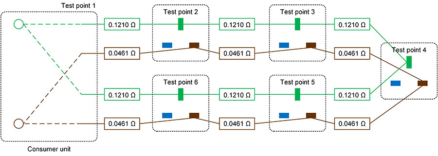
The resistances in Figure 1 are calculated from Guidance Note 3 Table B1 (at 20°C) as follows:
Resistance of 1.5 mm2 conductor = 12.1 mΩ/m
Resistance of 10 m of 1.5 mm2 conductor = 10×12.1 ÷ 1000 Ω = 0.1210 Ω
Resistance of 4.0 mm2 conductor = 4.61 mΩ/m
Resistance of 10 m of 4.0 mm2 conductor = 10×4.61 ÷ 1000 Ω = 0.0461 Ω
End-to-end tests (Step 1 of the ring final circuit continuity test)
Figure 2: End-to-end tests on the example circuit shown in Figure 1
The predicted readings for the end-to-end tests for r1 (line) and r2 (cpc) are:
r1 = 6 × 0.0461 Ω = 0.2766 Ω
r2 = 6 × 0.1210 Ω = 0.7260 Ω
Resistance measurement predicted by the formula (r1+r2)÷4 = (0.2766+0.7260)/4 Ω
or predicted reading by existing “rule of thumb” = (r1+r2)÷4 = 0.25 Ω
Step 3 of the ring final circuit test
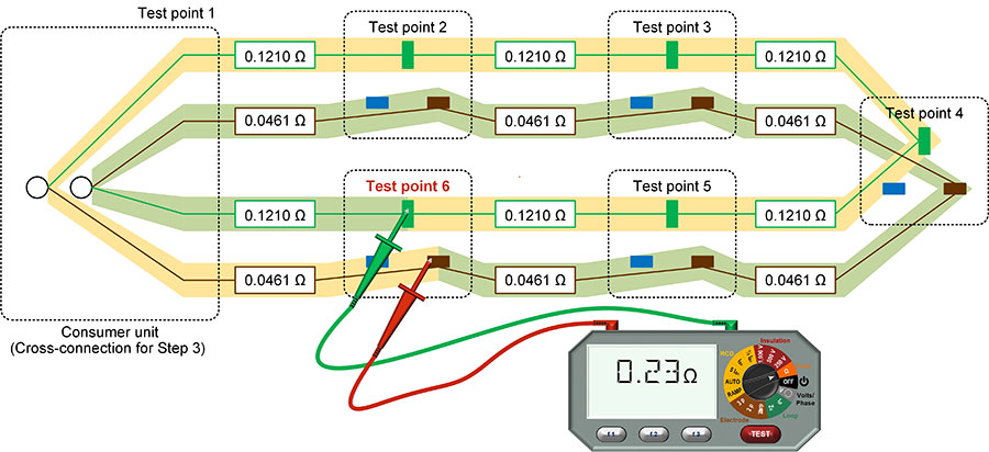
In Step 3, line and circuit protective conductors are cross-connected, and a resistance measurement is taken between line and circuit protective conductor at each point on the ring final circuit.
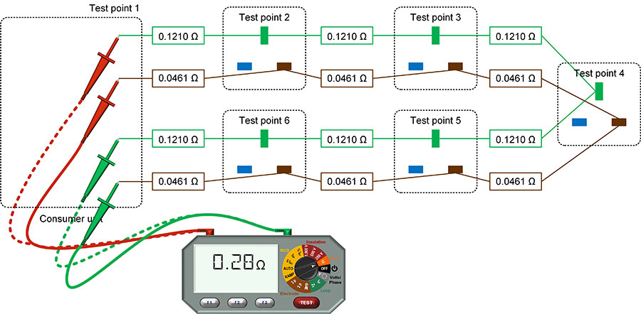
Step 3, resistance at Test Point 1
Figure 3: Resistance at Test Point 1 of the circuit illustrated in Figure 1
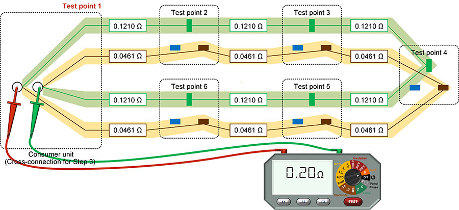
Resistance of yellow path ry = 6×0.0461 = 0.2766 Ω
Resistance of green path rg = 6×0.1210 = 0.7260 Ω
Using parallel resistance formula ry // rg = ry×rg ÷ (ry+rg), the predicted measured resistance is…
Predicted measured resistance = 0.2766×0.7260 ÷ (0.2766+0.7260) = 0.2003 Ω
Step 3, resistance at Test Point 2
Figure 4 Resistance at Test Point 2 of the circuit illustrated in Figure 1
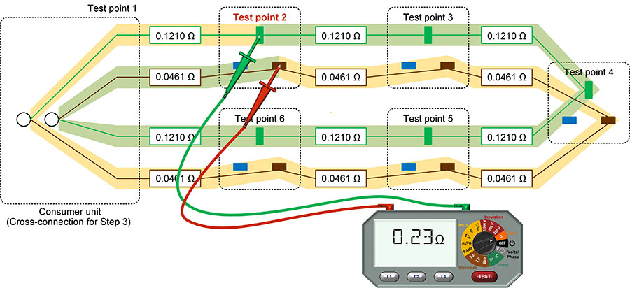
Resistance of yellow path ry = 5×0.0461 + 1×0.1210 = 0.3515 Ω
Resistance of green path rg = 5×0.1210 + 1×0.0461 = 0.6511 Ω
Predicted measured resistance = ry//rg = 0.3515×0.6511 ÷ (0.3515+0.6511) = 0.2283 Ω
Step 3, resistance at Test Point 3
Figure 5: Resistance at Test Point 3 of the circuit illustrated in Figure 1
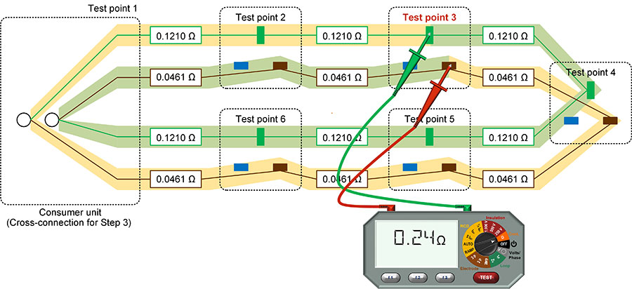
Resistance of yellow path ry = 4×0.0461 + 2×0.1210 = 0.4264 Ω
Resistance of green path rg = 4×0.1210 + 2×0.0461 = 0.5762 Ω
Predicted measured resistance = ry//rg = 0.4264×0.5762 ÷ (0.4264+0.5762) = 0.2451 Ω
Step 3, resistance at Test Point 4 (mid-point of the ring)
Figure 6: Resistance at Test Point 4 of the circuit illustrated in Figure 1
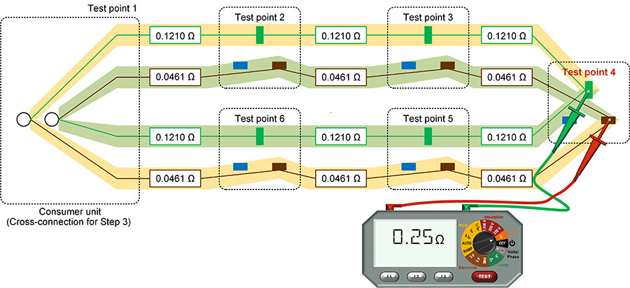
Resistance of yellow path ry = 3×0.0461 + 3×0.1210 = 0.5013 Ω
Resistance of green path rg = 3×0.1210 + 3×0.0461 = 0.5013 Ω
Predicted measured resistance = ry//rg = 0.5013×0.5013 ÷ (0.5013+0.5013) = 0.2507 Ω
Step 3, resistance at Test Point 5
Figure 7: Resistance at Test Point 5 of the circuit illustrated in Figure 1
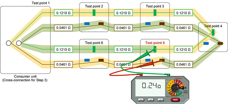
Resistance of yellow path ry = 2×0.0461 + 4×0.1210 = 0.5762 Ω
Resistance of green path rg = 2×0.1210 + 4×0.0461 = 0.4264 Ω
Predicted measured resistance = ry//rg = 0.5762×0.4264 ÷ (0.5762+0.4264) = 0.2451 Ω
Step 3, resistance at Test Point 6
Figure 8: Resistance at Test Point 6 of the circuit illustrated in Figure 1
Resistance of yellow path ry = 1×0.0461 + 5×0.1210 = 0.6511 Ω
Resistance of green path rg = 1×0.1210 + 5×0.0461 = 0.3515 Ω
Predicted measured resistance = ry//rg = 0.6511×0.3515 ÷ (0.6511+0.3515) = 0.2283 Ω
Results and conclusion
What is important for the person carrying out the inspection and testing is the predicted reading of the instrument, which is usually shown to two decimal places. The predicted readings from our example are shown to two decimal places in Table 1, alongside predicted readings for a 60 m ring final circuit wired in 2.5/1.5 mm2 cable calculated in the same way.
Table 1: Predicted readings at points around a 60 m ring final circuit
|
Test point |
Predicted instrument reading |
|
|
60 m ring wired in 2.5/1.5 |
60 m ring wired in 4.0/1.5 |
|
|
1 Origin of circuit |
0.28 Ω |
0.20 Ω |
|
2 Clockwise 10 m from origin |
0.29 Ω |
0.23 Ω |
|
3 Clockwise 20 m from origin |
0.29 Ω |
0.24 Ω |
|
4 Mid-point, 30 m from origin |
0.29 Ω |
0.25 Ω |
|
5 Clockwise 40 m from origin |
0.29 Ω |
0.24 Ω |
|
6 Clockwise 50 m from origin |
0.29 Ω |
0.23 Ω |
From Table 1, a 60 m 2.5/1.5 mm2 ring final circuit only shows a change of one in the least significant digit in the reading as you move around the ring, but with the same ring final circuit wired in 4.0/1.5 mm2, the change is five in the least significant digit on the instrument. This is a change of 25% of the lowest reading. The lowest reading deviates by 20% from the existing rule of thumb, and the highest reading is predicted by the rule of thumb. The longer the circuit, the more noticeable the difference in reading will be on a test instrument.
The type of readings observed with a ring final circuit using 4.0/1.5 mm2 cable might incorrectly be interpreted as a cross-connection or loose connection in the protective conductor of the circuit assuming that the results of Step 2 of the test are as expected, as more ring final circuits are wired in 4.0/1.5 mm2. This is somewhat different to the guidance published in the first eight Editions of IET Guidance Note 3 Inspection and Testing which stated that the readings at each point, should be substantially the same for Step 3, ignoring the effects of instrument accuracy, contact resistance and parallel paths.
Whilst existing guidance remains valid for ring final circuits formed with 2.5/1.5 mm2 cables, or single-core insulated cables in containment where the cpc has the same cross-sectional area as the line conductors, the 9th Edition of IET Guidance Note 3 Inspection and Testing will contain additional guidance and rules of thumb to account for line and circuit protective conductor combinations with larger differences in cross-sectional area, such as 4.0/1.5 mm2. The 9th Edition of IET Guidance Note 3 Inspection and Testing, which is due to publish in March 2022, is now available to pre-order via the IET Bookshop.
Addendum – If you don’t believe the mathematics
You can try an experiment for yourself without having to install 60 m of 4.0/1.5 mm2 for a ring final circuit. We can simulate a ring final circuit using 12 standard value resistors and a multimeter.
A good simulation of our example with similar values, but giving readings in kΩ instead of Ω, can be made using six 47 Ω and six 120 Ω resistors to represent the line and cpc conductors of the ring final circuit respectively. As shown in Figure 9, these can be connected as a cross-connected r1 and r2 as in Step 3 of the ring final circuit continuity test.
Figure 9: Simulation using 12 resistors
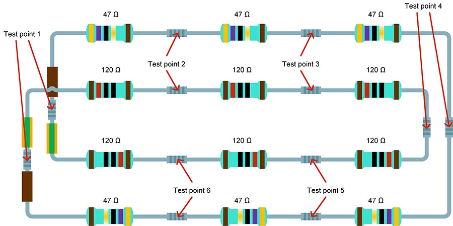
Set the multimeter to the kΩ range (if not auto-ranging), and measure resistances at the test points shown above, which mirror the test points in the earlier example.
The predicted readings are shown in Table 2. Note that the actual readings will vary slightly from the prediction, due to resistor tolerances and measurement accuracy, just as with a real ring final circuit test.
Table 2: Predicted readings at test points in the resistor simulation
|
Test point |
Predicted instrument reading (ignoring resistor tolerance and instrument accuracy) |
|
1 |
0.203 kΩ |
|
2 |
0.229 kΩ |
|
3 |
0.245 kΩ |
|
4 |
0.250 kΩ |
|
5 |
0.245 kΩ |
|
6 |
0.229 kΩ |
About the author
Graham, a Chartered Engineer and IET Member, is Managing Director of consultancy G Kenyon Technology Ltd and Chairs both the IET Wiring Regulations Policy Committee and Sub-Committee D of JPEL/64 of which he is a long-standing member. He is the technical author of a number of IET Guidance Notes and Codes of Practice, including the amendments to the 9th Edition of IET Guidance Note 3 Inspection and testing, due to publish in March 2022.