
Back to the Forum - The ring final circuit
As with all things, change is inevitable. The forum has transferred to a new platform called Engineering Communities. Despite the change of name, it is still the good old IET forum which we have come to love.
It has been decided to archive the old forum material. However, rather than letting all of those discussions gather dust, we have decided to create a new column in Wiring Matters looking at the ‘hot topics’. In this new column, we will return to items previously discussed on the forum and, looking to the future, will aim to discuss some of the current forum topics (where possible, adding in some history).
 Ring final circuits, more commonly and erroneously known as ‘ring mains’, have been debated since they were first installed. Like Marmite, you either love them or you hate them. Let’s take a look at some of the considerations.
Ring final circuits originated in the UK, for historic reasons dating back to 1942 and the reconstruction effort following World War Two.
The Post-War Building Studies Committee No.11 was convened by the Council of the Institution of Electrical Engineers in June 1942. It was tasked with making recommendations to facilitate the building of the one million houses predicted to be required in the aftermath of the war.
In the face of shortages of materials, ring final circuits were conceived, to minimize the amount of copper required. The 13 A socket-outlet with fused plug top to protect appliance flexes was also introduced at this time. It was said that the ring final circuit typically required 30% less copper and could save up to 25% in cost. This allowed 15 A sockets to be installed in all rooms cost-effectively.
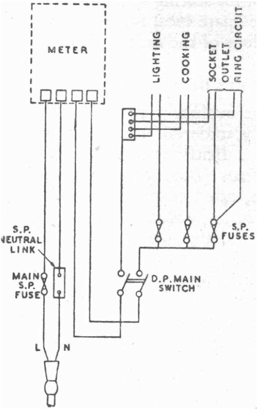
Not only do ring final circuits reduce the amount of copper required for cables to supply several sockets within the same area, but the size of the consumer unit required is also reduced. Back then, it was decided that a three-way fuse box would be sufficient for a small house, with a separate circuit for the lighting, cooker and socket-outlets.
The first appearance of ring final circuits in the IEE Wiring Regulations was in the 12th Edition, published in 1950. Regulation 201 stated that a:
“final sub-circuit in the form of a ring both ends of which are brought into the terminal of a fuse having a rating not exceeding 30 Amperes may serve not more than ten socket-outlets of 13 Ampere rating.”
It followed on with the exemption: “provided that in small houses or residential flats having a floor area not exceeding 1000 sq. ft. the number of socket-outlets served by such a ring circuit shall not be restricted”. This is where the 100 m² rule of thumb comes from, which is still used in guidance today (see IET Guidance Note 1 Selection & Erection, Appendix C).
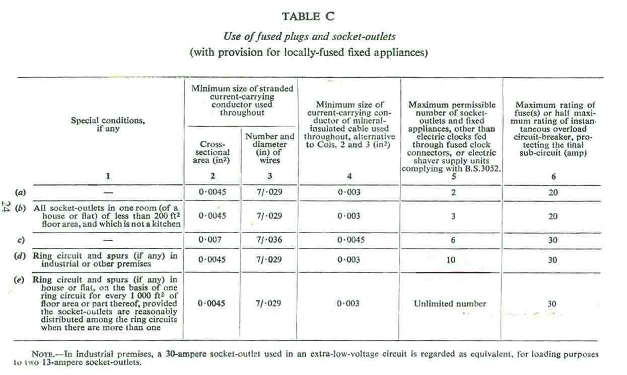
It was considered that a 30 A ring final circuit could supply a kettle and two electric heaters, which was sufficient for the householder. The minimum cable size required was 0.0045 sq. in., more commonly known as 7/.029 in. This is equivalent to 2.9 mm², so the nearest metric conductor size would be 2.5 mm².
Table C (below) is taken from the Thirteenth Edition of the IEE Wiring Regulations, it indicates the maximum permissible number of socket outlets, for the various types of circuits.
Circuits supplying socket-outlets should be designed according to their typical demand. Other than the kitchen, a modern dwelling is unlikely to have electrical equipment with a high power demand but will require several socket-outlets for convenience purposes. A radial circuit could, therefore, be considered appropriate.
Some say that the use of ring final circuits should stop, as they could be dangerous if any of the conductors become open circuit. Others argue that this is no different to a broken and undetected circuit protective conductor (CPC) on a radial circuit and that this reinforces the need to carry out inspection and testing on a regular basis.
It could be argued that ring final circuits are in fact safer: if a CPC breaks, there will be another conductor connected to earth, but the reduced cross-sectional area (CSA) may not be sufficient to provide automatic disconnection within the required time.
It is true, however, that if ring final circuits are added to or altered incorrectly, a dangerous situation could occur with regard to overloaded cables. Other issues with ring final circuits include cross-connections between two different final circuits, resulting in two devices being required to isolate the circuit and increased disconnection times.
Summary
In summary, ring final circuits can be a cost-effective way of providing socket-outlet circuits and, like any other installation, are safe if designed, installed and maintained properly. However, continuity testing of ring final circuits can be time-consuming and requires the electrical supply to be isolated during testing, involving downtime. The installation of two radial circuits will take less time and use less cable than one ring final circuit, and this compensates for the additional protective device.
BS 7671:2018+A1:2020 permits both ring final and radial circuits to supply socket-outlets and each method should, therefore, be judged on its merits.