
Earth fault loop impedance revision of ENA Engineering Recommendation P23
The Energy Networks Association (ENA) recently published engineering recommendation (ER) P23/2:2018 Guidance on Earth Fault Loop Impedance at Customers’ Intake Supply Terminals, which supersedes ENA ER P23/1:1991 Consumers’ earth fault protection for compliance with the IEE Wiring Regulations for Electrical Installations.
Industry has for many years been using the ‘maximum values’ of Ze published in ENA ER P23/1 1991. The values of Ze for supplies up to 100 A are shown in Table 1.
Table 1: Values of Ze for 230 V single-phase TN and TT supplies not exceeding 100 A according to ENA ER P23/1:1991
|
Supply arrangement |
Ze |
|
TN-C-S (Note 1) |
0.35 Ω (Note 2) |
|
TN-S |
0.8 Ω (Note 2) |
|
TT |
21 Ω (Note 3) |
- Note 1: In ENA ER P23/1:1991, this value was quoted for both Protective Multiple Earthing (PME) and Protective Neutral Bonding (PNB) earthing arrangements. Higher values may apply where the consumer was supplied from small capacity pole-mounted transformers and/or long lengths of low voltage overhead line.
- Note 2: The external earth fault-loop impedance for TT systems consists of the resistance of the neutral to earth plus the impedance of the transformer winding and line conductor, but does not include the resistance of the consumer's earth electrode.
The values in Table 1 have served as a reliable guide since their publication, although it has always been recognised that a small number of installations may fall outside these parameters, and represent an over-estimate (on the side of caution) for the majority of installations. They were never guaranteed for all installations, and for this reason, BS 7671 requires Ze be validated (by measurement or another valid method) during verification.
The changes in ENA ER P23/2:2018
ENA ER P23/2:2018, contains a set of values based on PD IEC/TR 60725:2012 Consideration of reference impedances and public supply network impedances for use in determining disturbance characteristics of electrical equipment having a rated current ≤ 75 A per phase. The quoted values for existing supplies up to 100 A are shown in Table 2.
Table 2: Values of Ze for existing 230 V single-phase supplies not exceeding 100 A according to EA ER P23/2:2018
|
Ze |
Comment |
|
0.34 Ω (0.25+j0.23) |
90% of premises will have an EFLI below this value. |
|
0.64 Ω (0.46+j0.45) |
98% of premises will have an EFLI below this value. |
|
Over 0.64 Ω
|
2% of premises will have an EFLI above 0.64 Ω. |
- Note 1: These are typical maximum values and the measured value of Ze will change depending on the network configuration due to alterations, faults, maintenance and any embedded generation.
- Note 2: Distribution network operators (DNOs) are under no obligation to design or maintain networks to provide a particular maximum value of Ze. Many DNOs do, however, have their own internal quality and design standards, which often align with the Ze values in Table 1.
- Note 3: The values for new networks are available from the DNO.
- Note 4: The typical maximum Ze quoted in P23/1 was 0.8 W for a TN-S service with a capacity of up to 100 A.
What to use for calculations in installations with single phase supplies up to 100 A
The IET recommends that designers continue to use the values in Table 1 of this article, for public TN supplies up to 100 A, unless alternative recommendations are provided on enquiry with the DNO. It is recognised that this will now, as previously, provide an over-estimate for many installations, but this helps safeguard the design against future changes in transmission and distribution systems, and when embedded generation is added.
The IET also recommends using a calculation value for maximum prospective fault current of 16 kA for single phase supplies up to 100 A where the service cable exceeds 2 m in length, unless the DNO recommends an alternative value.
BS 7671:2018 requires that Ze and Ipsc are ascertained by measurement or another valid method during initial and periodic verification, to validate that disconnection times can be achieved for automatic disconnection of supply.
These recommendations will be reflected in the suite of IET guidance publications that accompany the 18th Edition of the IET Wiring Regulations, including:
- The On-Site Guide (IET Wiring Regulations 18th Edition)
- Student's Guide to the IET Wiring Regulations, 2nd Edition 2018
- Guidance Note 5: Protection against electric shock, 8th Edition 2018
- Guidance Note 6: Protection against overcurrent, 8th Edition 2018
- Electrical Installation Design Guide, 4th Edition 2018
Further information can be found in the relevant guidance publications.
Why is Ze important for designers?
In design practice, the circuit length for a given cable cross-sectional area (csa) is limited by one of the following constraints:
- The maximum Zs for the circuit protective device used for fault protection to achieve disconnection times proscribed by Table 41.1 of BS 7671.
- The adiabatic criterion in relation to protection against damage due to overcurrent faults in accordance with Regulations 434.5.2 and 543.1.3
- Voltage drop.
The first of these constraints requires some consideration of Ze., and the last relates to prospective fault current Ipsc.
The earth fault loop impedance Zs for a radial final circuit is given by:
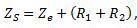 where
where
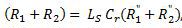 and
and
Ls is the maximum length of the radial circuit in m to achieve automatic disconnection in accordance with Table 41.1 of BS 7671, and
 is the 'volt-drop' resistance in mW/m of the cable from Appendix 4 of BS 7671.
- Zs is the maximum earth fault loop impedance Z41 from the relevant Table 41.2, 41.3, 41.4, or, where Regulation 411.4.9 applies, Table 41.5.
Substituting these values, we see that for radial final circuits 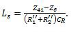
Similarly for ring final circuits, 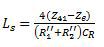
Note: See Section 2.6 of the IET’s Electrical Installation Design Guide for a more in-depth discussion on these equations, and examples of how they are used.
With the exception of Ze all of these values are available for the designer to adjust by selection, and using data from the relevant tables in BS 7671. We can see that, as Ze increases, the maximum length of the circuit that will achieve the required disconnection time decreases.
The distribution system itself undergoes changes over time. There are two key issues that should be considered:
- When some TN-S distribution systems are repaired, this must be done with combined neutral and earth (CNE) cable. In this case, additional earth electrodes are installed in the distribution system, and the distribution becomes, at least in part, TN-C-S. For this reason, it might be recommended to treat TN-S installations in the same manner as TN-C-S installations; however, they may still have a Ze > 0.35 Ω
- Other network changes may mean that values Ze and prospective fault current Ipsc measured at the time of the previous verification and validation have changed over time.
Importantly, Ze may increase as the changes are made. It is therefore necessary to check Zs for circuits during periodic verification, by measurement or another valid method.
Graham is Managing Director and Principal Consultant, G Kenyon Technology Ltd
Chair, IET Wiring Regulations Policy Committee Deputy Chair, JPEL/64 (IET Wiring Regulations) Sub-Committee D (Special locations and external influences)