Part 2 - Exploring wiring systems for unearthed DC solar PV systems
In Part 1 of “Exploring wiring systems for unearthed DC solar PV systems” in Wiring Matters Issue 104, the use of newly developed cable comprising insulated and sheathed cables with a steel wire armour (SWA) construction was considered and it was concluded that such cables, when buried direct in the ground, did not meet the requirements of BS 7671:2018+A2:2022+A3:2024.
This second article looks at some other design considerations for SWA-type cables on the DC side when not buried. It also investigates the safety features of a modern-day inverter and the options a designer has when considering a departure from BS 7671:2018+A2:2022+A3:2024.
What protective measures can be used where insulated and sheathed cable with an SWA construction is selected?
In Part 1, it was established that standard SWA cables manufactured to BS 5467, BS 6724 or BS 7846 do not meet the requirements for wiring systems suitable for use with the protective measure double or reinforced insulation, since the filler material (bedding) does not have insulating properties. See “Mythbusters #4 Double insulated cables” in Wiring Matters Issue 75.
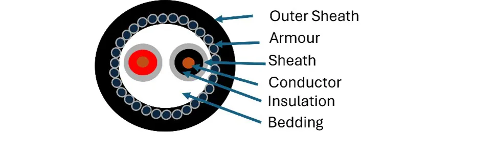
The development of new cables whereby a metallic sheath, or armouring, is applied to an insulated and sheathed cable (see Figure 1) requires careful consideration since the requirements for the protective method adopted for protection against shock in solar PV systems is given in Regulation 712.410.102 of BS 7671:2018+A2:2022+A3:2024, which states:
“On the DC side, one of the following protective measures shall be applied:
(i) double or reinforced insulation (Section 412)
(ii) extra-low voltage (SELV or PELV) (Section 414).”
The protective measure referred to in indent (i) is intended to prevent shock caused by the appearance of dangerous voltages on accessible parts of electrical equipment through the failure of basic insulation. There is also the additional concern of arcing where a second fault in insulation on the other pole occurs, which could cause a fire.
Figure 1 Non-standard SWA comprising insulated and sheathed cores contained within an armour constructed cable
This is reinforced by Regulation 712.521.101 of BS 7671:2018+A2:2022+A3:2024 which states:
“Cables on the DC side shall be selected and erected so as to minimize the risk of earth faults and short-circuits. This shall be achieved by using:
(i) single-core cables having a non-metallic sheath, or
(ii) insulated (single-core) conductors installed in individually insulated conduit or trunking. Cable(s) shall not be placed directly on the surface of the roof.”
The intent of this regulation is to minimize the risk of earth faults and short-circuits brought about by a cable being damaged and the live conductors being bridged together or coming into contact with metalwork. With this in mind, a designer must consider if a cable, where its construction is surrounded by metal, is suitable when using double and reinforced insulation as a protective method.
Furthermore, where suitable cables are in contact with metalwork, such as insulated and sheathed cables on cable tray or within cable trunking, a designer should ensure that there is minimal chance of damage by impact, abrasion or subsequent flexing during and after installation.
This may be counterintuitive to a designer who regularly uses earthed metallic containment where there is a chance of impact (such as meeting the requirements of indents (i) to (iii) of Regulation 522.6.204 of BS 7671:2018+A2:2022+A3:2024. These methods are only suitable where automatic disconnection of supply (ADS) is the protective measure.
Regulation 712.410.102 of BS 7671:2018+A2:2022+A3:2024 states that only one protection method is to be used, and ADS is not listed as one of the acceptable methods. If a protection method that was not listed was to be employed, this would be a departure from BS 7671 and is explored further in this article.
Can insulated and sheathed cable with a steel wire armour increase safety by protecting cables from damage by rodents above ground?
The presence of an armoured sheath will likely reduce the immediate loss of service brought about by cables and conductors being chewed through, but such damage will need to be repaired regardless and is therefore not a cost-effective solution.
If the external influence is fauna, such as rodents, a preventative method may be a better option and should be considered. Options to consider may be selecting alternative cable routes or applying additives to coverings (such as capsaicin). The use of additives would also require confirmation from the cable manufacturer that there would be no detriment to safety and performance of the cable. It is common to use mesh and netting around PV arrays to prevent damage from fauna. Any ducts should be suitably sealed, and cables can run through other containment in high-risk areas. The PVC outer sheath of an SWA cable is not designed to be sacrificial as it often provides a barrier against water ingress.
ADS cannot be used on the DC side of the installation and conform to BS 7671. Can this protection method be utilized and recorded as a departure?
Modern inverters have a number of built-in additional safety features as described in BS EN 62109-2:2011 Safety of power converters for use in photovoltaic power systems, that reduce the risk of electric shock and fire by switching off the inverter and stopping current flow in the DC strings, but this does not remove the potential from the strings. These features can include:
- DC reverse polarity protection
- insulation monitoring
- residual current monitoring
- arc fault detection
- AC overcurrent
- AC overvoltage
- AC short circuit protection
- anti-islanding protection.
These protective features are typically instigated upon start-up (or ‘wake-up’) of the inverter. Whilst an inverter may indeed shut down where a fault occurs on insulated and sheathed cables with an SWA construction, the solar PV modules (or panels) will continue to generate and voltage will remain present on the armouring, therefore, disconnection of supply will not be achieved.
Can PV DC power optimizers or other devices provide ADS on the DC side?
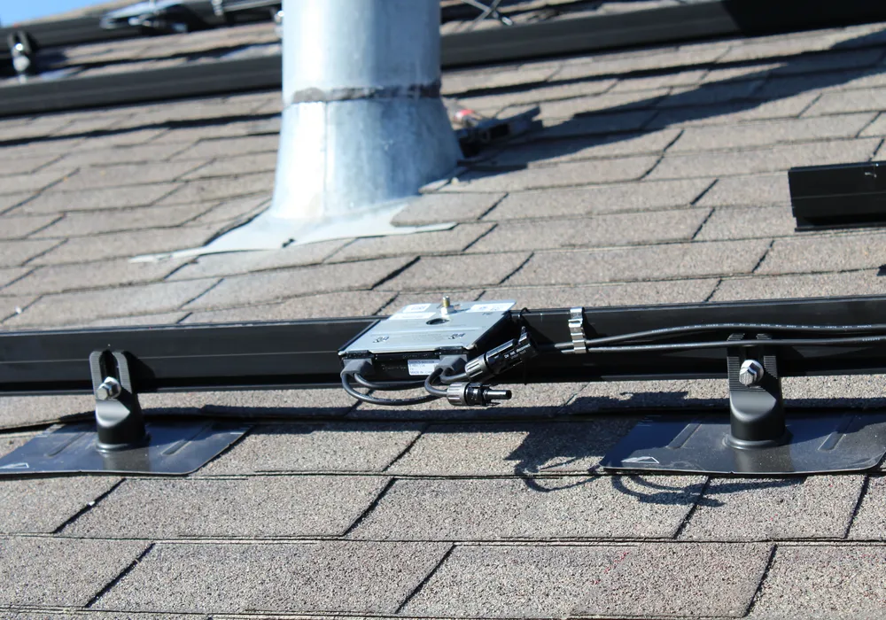
It is to be noted that PV DC power optimizers are not recognized as a method of protection in BS 7671, however, they may provide benefits such as increased module performance and offer proprietary module shut-down options. These devices are module level electrical units that condition the output of a PV module or modules. Some are able to reduce the voltage and current in a string to a safe level when the inverter has detected certain faults.
Figure 2 PV DC optimizers fitted to solar rails prior to installation of PV modules
Nevertheless, the time taken for these devices to operate can be up to 30 seconds and their operation is dependent upon the inverter shutting down. The same is also true of firefighter safety switches; devices which can be used to switch off arrays or strings to reduce voltages in the event of a fire. The disconnection times are designed to protect against fire, not electric shock. Furthermore, the safety mechanisms built into the inverter also vary in the time taken to effect shut down and some only occur at wake up when the inverter starts to operate due to daylight being present. Thus, complying with the requirements for ADS associated with Regulation 411.3.2 of BS 7671:2018+A2:2022+A3:2024 for example, would be difficult to achieve.
Examples of disconnection times taken from BS EN 62109-2-2011 Safety of power converters for use in PV power systems, are shown in Table 1.
Table 1 Examples of disconnection times taken from BS EN 62109-2-2011
| BS EN 62109-2-2011 reference | Type of monitoring | Frequency of monitoring | Time to effect disconnection of inverter |
| 4.4.4.15.1 | Residual current monitoring | Before starting operation | Hours |
| 4.8.1 | Array ground insulation resistance test | Before starting operation | Hours |
| 4.8.3 | Array residual current detection | Ongoing either by use of a 30 mA RCD or continuous monitoring for excessive residual current or excessive changes | 40 – 300 ms depending on leakage current |
Unearthed DC solar PV systems sometimes have conductors not forming part of the DC system attached to them. What is their purpose?
To answer this, it is useful to understand how an inverter works in conjunction with unearthed DC systems. Solar PV inverters in the UK are commonly transformer-less which means there is no simple separation between the AC and DC sides of the PV system. The inverter works electronically and effectively uses switching transistors to create an AC waveform from the DC supply produced by the PV modules.
Unearthed systems are not entirely without connection to the general mass of Earth since the system will be linked to Earth via capacitive coupling. It is called an unearthed system because there is no designed physical connection to Earth. In such systems, earth fault currents are very small and difficult to measure. The small currents mean it is safer for people and livestock and there is less risk of arcing since two conductors are needed to carry the current. This reduces the risk of both electric shock and fire.
Where ground mounted systems are accessible to persons and livestock, the designer may consider connecting the array frame to Earth, reducing the chance of touch voltages. Wet weather, aged PV modules and single-phase transformer-less inverters greater exhibit this phenomenon which is known as parasitic capacitance.
It is important to note that the connection to the Earth in this instance is not forming part of a protection method as there is no protective device that can operate to provide disconnection. It is effectively operating as a method of substantially equalizing the potentials to eliminate touch voltages between the general mass of Earth and the associated metalwork of the PV array. In this instance, the connection is working as equipotential bonding.
In some countries, inverters with transformers are used. Where these are used, it is common to see earthed DC systems, and capacitive coupling does not occur.
Another phenomenon that can occur is potential induced degradation (PID). This reduces the power output of a cell and occurs when the voltage between the PV cells and the Earth drives ions from the module glass into the semiconductor material of the solar PV cells. Damage occurs with cells at the negative end of the string being most affected. High system voltages, poor quality panels, location and climate can all exacerbate this effect. One method of combating this is to use anti-PID technology that introduces a temporary earth connection during the night. In this instance, the earth connection is not providing protection by disconnection but is working as a functional earth.
In short, although unearthed DC solar PV systems may have associated conductors, the conductors do not form part of the protective measure ADS.
If a designer selects insulated and sheathed cable with an armoured construction, should the armour be connected to the AC or DC earthing?
In the case of an unearthed DC solar PV system, the armour could not be connected to earth on the DC side since there isn’t any.
Connecting the armouring to the AC side earth would not achieve ADS. Additionally, if a fault were to occur, such that the DC cables were bridged to the armouring, this could lead to distribution of live DC potential to parts of the AC system with a detrimental impact on RCDs on the AC side, as well as malfunction and damage to other components. At the time of writing this article, there is no knowledge of inverter manufacturers undertaking type testing of earthed DC cables and the effects on modern inverters and users.
Designers may consider using insulated glands, leaving the armoured sheath isolated from any connection to earth. In the event that mechanical damage occurred, such that one of the DC conductors bridged to the armouring, the user of the installation would be at risk of a shock if they unwittingly touched both the opposite pole conductor and the armour. Whilst an inverter may detect such a fault, suitable disconnection times would not be met and in the absence of devices such as optimizers, the armour would remain at a hazardous voltage. In any event, putting aside the concern of a lethal voltage appearing on the armourings due to mechanical damage, there is also a risk that a non-lethal perceivable voltage could appear on the armouring due to cable capacitance. All cables experience capacitance which occurs when two conductors separated by a distance can store a charge. Having a metallic screen over a cable introduces a further capacitance. Just as a potential can appear on PV arrays due to parasitic capacitance, the same can occur with the armour of a cable. To eliminate the risk of a user experiencing a perceivable potential (which could be dangerous if this was to occur to someone on a ladder, for example), the designer would need to ensure the armour was indeed earthed.
The IET Code of Practice for Grid-connected Solar Photovoltaic Systems, 2nd Edition, states in Section 5.10.3, Note 3:
“Suitable methods of mechanical protection for cables concealed in walls or building fabric may include the use of earthed metallic conduit or trunking. Cables within the metallic containment are still required to meet the requirements for double or reinforced insulation.”
In the case of newly developed cable comprising insulated and sheathed cables with a SWA construction, the armour is arguably acting as metallic containment of sorts and for this reason, it would be better to attach the armour to the earthing system, eliminating the risk of touch potentials.
The introduction of an earthed armour may also lead to problems with leakage currents being detected by insulation resistance monitoring equipment, although this would likely be more of an issue on large-scale installations rather than small-scale domestic designs.
Is BS 7671:2018+A2:2022+A3:2024 failing to keep up with innovations?
The UK Wiring Regulations stem from international (IEC) and harmonized (European, HD) standards known as the 60364 series. The IEC and HD standards can take many years to draft and implement, and take into account global and European best practices, products and safety concerns. Once published as an international standard (IS), the technical intent must be adopted by our national committee (JPEL/64) within three years into BS 7671.
It is impossible for the Wiring Regulations to keep up with rapidly changing technology and in recognition of this, Regulation 133.1.3 permits the use of equipment outside the scope of the standard, providing the designer responsible for specifying the installation confirms that the equipment provides at least the same degree of safety as that afforded by compliance with the regulations. Designers must be mindful that sometimes seemingly small, innocuous changes to installation methods can have unintended consequences. Consultation with the relevant manufacturer(s) is imperative and they should provide declarations of equivalent safety and conformity backed up by credible research and data. It is important that the designer bears in mind that in the event of an accident, they may be required to justify their decision in a court of law. (See “Intended departures from BS 7671” in Wiring Matters Issue 106.)
Users of the standard are invited to write to the committee in charge of writing the standard, JPEL/64, at any time. You can contact the committee by registering via the BSI Standards Development Website.
Summary
Traditional wiring systems that conform to BS 7671:2018+A2:2022+A3:2024 can be used on the DC side of an installation. Designers may depart from these requirements to enable innovation, provided they can demonstrate that the alternative solution is no less safe than implementing the requirements stated in the wiring regulation and provide confirmation that the products meet The Electrical Equipment (Safety) Regulations 2016 with supporting technical documentation.
Safety functionality built into inverters is generally designed to protect the equipment itself and not persons and livestock. As a result, it is not often designed to provide disconnection in a time scale suitable to provide shock protection. Where the inverter is shut down rapidly, voltage will remain present on the strings at up to 1,500 V DC. The use of PV DC power optimizers will limit the voltage at the source of supply (PV modules) after a period of time, although this does not guarantee disconnection times are met.
SWA cables are sometimes specified to guard against rodent damage, but other wiring methods may eliminate that risk more effectively. When SWA is used, its armour often serves as the protective conductor; however, bonding DC cables to earth through the armour can, in some cases, reduce overall safety.
Other newly designed cables such as those with insulated and sheathed cables wrapped in a ‘tough sheath’ may be used in compliance with BS 7671:2018+A2:2022+A3:2024 alongside established installation methods.
Using products that fall outside recognized standards demands careful evaluation; they may be appropriate in certain situations but rarely in all.
Acknowledgements
- Brian Abbott
- Calum Mansell
- Craig O’Neill
- Darren Crannis
- Gary Gundry
- Graham Kenyon
- Dr Jeremey Hodge
- Joe Cannon
- John Peckham
- Leon Markwell
- Mark Coles
- Michael Peace.