Bidirectional protective devices
This article looks at the selection and erection of protective devices for other sources, such as PV and electrical energy storage systems, as highlighted in the recently published BEAMA bulletin Connection of unidirectional and bidirectional protective devices.
What is a unidirectional protective device?
Unidirectional protective devices are marked to indicate the line and load terminals and are designed to work when the power can only flow in one direction, i.e., from supply to load. It is vital to observe the connection details.
Single-module sized residual current breakers with over-current protection (RCBOs) have been available for several decades and utilize electronic circuits to provide residual current protection. These compact RCBOs contain electronic components and are typically unidirectional. Arc fault detection devices (AFDDs) are also typically unidirectional.
The product standard for RCBOs states that if it is necessary to distinguish between the supply and load terminals, they shall be clearly marked, for example, by line and load placed near the corresponding terminals or by arrows indicating the direction of power flow. Therefore, if a device is marked line, load, with arrows etc, it is indicating that it is necessary to distinguish between the supply and the load terminals. Not all compact RCBOs are unidirectional. Some RCBOs employ technology/solutions that ensure that the RCBO is not damaged when supplied in either direction and these are bidirectional.
What is a bidirectional protective device?
A protective device that does not have markings to indicate line and load terminals is a bidirectional device, where power flow in either direction will not cause damage.
The 'typical' residual current circuit-breaker (RCCB) is an electromechanical device, however, electronic RCCBs also exist. RCCBs for consumer units are in the form of a two module-sized device. These devices are not usually marked in and out, and therefore are bidirectional. In some cases, RCCBs are marked to indicate the terminals to which the neutral or line should be connected.
Single-phase RCBOs are available in a single module, known as ‘compact’, and two module sizes. Two module RCBOs are not usually marked as with circuit-breakers (CBs), and thus are also bidirectional.
How are unidirectional protective devices marked?
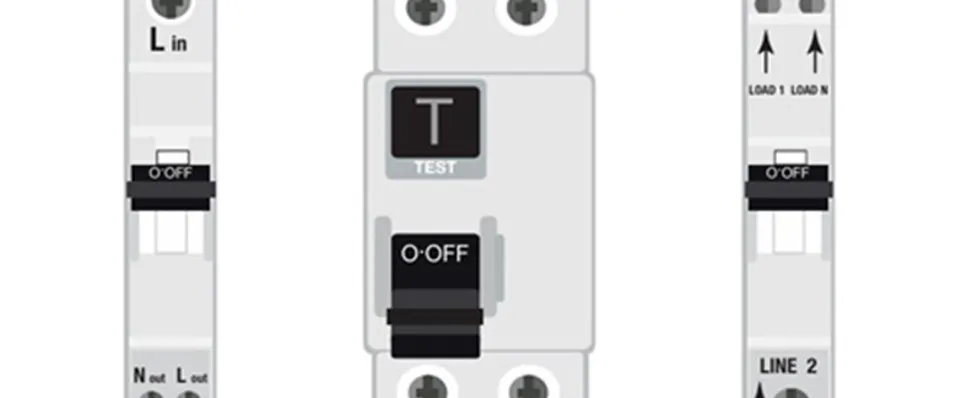
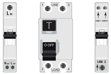
Where required, protective devices such as CBs, RCCBs, RCBOs and AFDDs feature a marking on the device to distinguish between the supply and load terminals. This can be marked in a number of ways such as, line and load, in and out, or by using directional arrows to indicate the power flow. The connection details are shown in Figure 1.
Figure 1 Protective device connection details
Can unidirectional protective devices be used for other sources, such as PV systems?
In addition to Section 712 of BS 7671:2018+A2:2022, PV systems are also covered in Part 8 of BS 7671:2018+A2:2022 which covers prosumer’s electrical installations (PEI). Regulation 826.1.2.2 states current flow and polarity should be taken into account. As with all electrical equipment, it is important to take account of manufacturer’s instructions, Regulation 134.1.1 and 510.3 of BS 7671:2018+A2:2022 refers.
Where an additional source in parallel to the low voltage (LV) electrical supply is present, such as a PV generator in, the installer is faced with a dilemma. The issue is that it is not possible to follow the line and load convention where two supplies are present.
Unidirectional protective devices should not be used for such power sources as the power flow could be in either direction. Applying a power source to the load terminals of a unidirectional RCCB/AFDD will, under certain circumstances, result in damage to the electronics, rendering the residual current protection inoperable.
Doesn’t the inverter shut down automatically in the event of a short circuit or loss of mains?
The power electronic converter system (PECS), or more commonly known as the inverter, is designed to shut down, very quickly, typically milliseconds, in the event of a fault or loss of supply. The maximum trip time for loss of mains for modern PV inverters, according to EREC G98, is up to 0.5 seconds, however, some older PV inverters may have a trip time of up to 2.5 seconds.
The concern highlighted by BEAMA is that a voltage present on the outgoing terminals of the protective device, either due to the device operating in the event of an earth fault or by use of the functional test button, could cause irreparable damage.
Are residual current devices (RCDs) required for PV systems?
RCDs are not required for PV systems per se, but they may be required for other reasons, such as fault protection in TT systems or for additional protection where the AC PV inverter supply cable is buried in a wall.
The majority of PV systems are likely to be retrofit, where the cable used for the AC PV inverter supply circuit is installed surface mounted using steel wire armoured (SWA) cable. Therefore, RCD protection would not be required for additional protection in this case.
Some manufacturers discourage the use of RCDs for inverters due to leakage currents. Where possible, it is best to design it out and provide other methods of protection where required.
Where RCDs are required for generators intended to be used in parallel with the distribution network, it is important to ensure they are bidirectional.
How does this affect existing installations?
When considering existing installations, such as when carrying out an electrical installation condition report (EICR), it is important to keep things in perspective. If the electronic circuit within a RCBO was damaged by voltage on the outgoing terminals, the thermal/magnetic part of the device would still operate, providing overload and short-circuit protection.
For TT systems, RCDs are installed to provide fault protection for the protective measure with automatic disconnection of supply (ADS). Failure of the RCD could be a serious safety issue and would require urgent remedial action.
In a situation where an RCD has been installed for additional protection, such as for cables buried in a wall, if the RCD were to fail, it would be a no more dangerous situation than an electrical installation from BS 7671:1992, the Sixteenth Edition of the IEE Wiring Regulations, when additional protection was not included in the standard at that point.
It’s important to remember that the requirements of the latest version of BS 7671 are not retrospective. The Electrical Safety First (ESF) Best Practice Guide (BPG) 4 guidance states that a recommendation for improvement is appropriate for the absence of an RCD for cables buried in a wall. However, the inspector must make an engineering judgement based on the situation.
The guidance in the BEAMA Technical Bulletin is that “proportionate action” is required and it is recommended to contact the protective device manufacturer, seeking their advice as to the correct course of action.
Other considerations for RCD selection for generators
It can be easy to think only of Section 712 when considering PV systems. It sometimes gets overlooked that PV systems are in fact generators, which are covered in Section 551 of BS 7671:2018+A2:2022, and it is important to remember that the general requirements also apply.
Regulation 551.7.1 of BS 7671:2018+A2:2022 provides requirements where a generating set may operate in parallel with the distribution network, such as a PV system. It states that where an RCD is providing additional protection in accordance with Regulation 415.1 for a circuit connecting the generator set to the installation, the RCD shall disconnect all live conductors, including the neutral conductor. This can be in the form of a double-pole or single-pole with switched neutral protective device. It is important to check as some compact RCBOs are only available as single-pole devices. This requirement has been included in BS 7671:2008.
It is important to select the correct type of RCD according to DC residual current to prevent the RCD being blinded. Regulation 712.531.3.5.1 of BS 7671:2018+A2:2022 provides requirements for RCDs for solar photovoltaic (PV) power supply systems. It states that where an RCD is used for protection of the PV AC supply circuit, the RCD shall be of Type B according to BS EN 62423 or BS EN 60947-2, unless the inverter or installation provides at least simple separation between the AC and DC side or the inverter does not require a Type B RCD as stated by the manufacturer, based on their instructions.
Summary
Bidirectional power flow of generators or energy storage systems must be considered when selecting protective devices. Unidirectional protective devices are not suitable for other sources, such as PV and battery storage systems.
There is no requirement for RCDs for PV systems as such, however, this is dependent upon the installation characteristics. To avoid unwanted tripping due to leakage currents, design the circuit in such a way that RCD protection is not required.
Where RCDs are required for PV systems, they must switch all live conductors, including the neutral. It is important to select the correct type of RCD according to the expected level of DC residual current to prevent blinding, where a Type B would be most suitable. It is important to take account of manufacturer’s instructions.
The product standard for RCBOs states that if it is necessary to distinguish between the supply and load terminals, they shall be clearly marked for example, by line and load placed near the corresponding terminals or by arrows indicating the direction of power flow. It is important to check with the manufacturer of the protective devices to confirm their suitability for bidirectional power flow.
Acknowledgments
I would like to thank the following individuals for their contributions to this article:
- BEAMA
- Frank Bertie (NAPIT)
- Neil Bridgeman (RIA)
- Mark Coles (IET)
- Darren Crannis (ECA)
- Jon Elliot (Certsure)
- Leon Markwell (IET)
- Craig O’Neill (IET)
- Gary Parker (ECA)
- SELECT
Further reading
BEAMA Technical Bulletin - Connection of Unidirectional and Bidirectional Protective Devices