Polarity indication on boats – why it’s important to get it right!
The purpose of this article is two-fold: firstly, to explore an element of the world that exists on the other side of the supply interface defined in Section 709 of BS 7671 ‘Marinas and Similar Locations’ and secondly, to announce the impending publication of a new IET publication: The On-Board Guide to Electrical Safety for Small Craft.
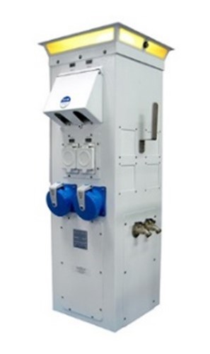
To set the scene, it is necessary to provide some insight into the differences between the requirements for land and water-based electrical installations. From a BS 7671 perspective, the Section 709 ‘boundary’ terminates at the BS EN 60309 fixed outlet connectors located on the power bollard/pillar found at many mooring locations (see Figure 1). Furthermore, Section 709 of BS 7671 also emphasises that electrical supplies in the marine environment attract an increased risk of electric shock due to the (obvious) presence of water, reduced body resistance, and an increased probability of body contact with earth potential.
Figure 1 Power bollard/pillar
By contrast, the Section 708 of BS 7671 ‘Electrical Installations in Caravans/Caravan Parks and Similar Locations’ ‘boundary’ encompasses not only the caravan pitch socket-outlet(s) but also includes a definition of the assembly configuration of the cable which connects the caravan to the caravan pitch electrical supply socket-outlet.
It may come as a surprise to some that the shore-power cable that is used to connect the BS 7671-defined power bollard/pillar to a boat’s appliance inlet connector is not defined in the same manner as Section 708. To illustrate this point, while marine electrical standard BS EN ISO 13297 Small craft – Electrical systems – Alternating and direct current installations does use the terms ‘shore-power cable’ and ‘shore-power appliance inlet’, it is left to the reader of this standard to form a mind‑picture of the composition of a typical shore-power cable. Equally surprising is the fact that a shore-power cable is rarely supplied by the boat builder as it is regarded as an owner‑supplied item in the same vein as mooring ropes!
Regardless of who supplies the craft’s shore-power cable, ISO 13297 does require a statement on the safe use of such cables to be provided by the boat builder in the ISO 10240 mandated (boat) Owner’s Manual; however, this too falls short on cable configuration detail and specific testing requirements.
By contrast, Clause 5 of IEC 60092 – 507 Electrical installations in ships – Part 507 – Small Vessels, provides a comprehensive oversight of shore connection arrangements and is recommended as the ‘go-to’ reference on this topic.
Faced with a poorly defined boat power electrical interface (from the ISO 13297 perspective), we now need to understand the role and function of polarity indicators fitted to small craft and how incorrect implementation can create issues that are not found in land-based installations. To avoid over-complication, the remainder of this article will only consider polarized AC supplies in metal-hulled craft.
To ensure “proper operation of the electrical devices in the system”, ISO 13297 not only requires that “the polarity of the system is maintained”, but also requires “fitment of a reverse polarity indicator in shore-power systems that provides a continuous visible or audible signal that responds to reversal of the active (line) and neutral conductors”. To provide a visual and/or audible reverse polarity indication, a 230 V neon indicator and/or 230 V buzzer is normally connected between the incoming supply neutral and protective conductors (PE), thereby providing a positive indication of L-N reversal.
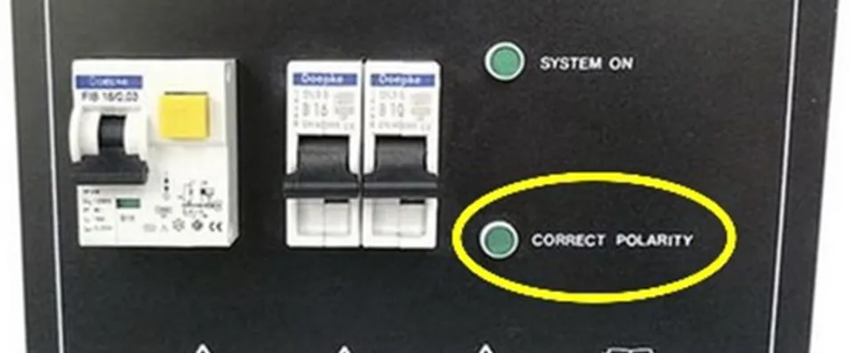
While ISO 13297 provides no guidance on the location of any reverse polarity indicator, it should be noted that some suppliers of ready‑made 230 V AC panel boards, have, (for reasons best known to themselves), decided to fit a ‘polarity correct’ indicator – see circled area of Figure 2. If you’ve already ‘joined the dots’, you’ll have realized that such indicators need to be connected between the incoming supply line and PE conductors to function in the manner described on the caption and are therefore non‑compliant to the requirements of both ISO 13297 and IEC 60092-507.
Figure 2 230 V AC panel board with a polarity indicator

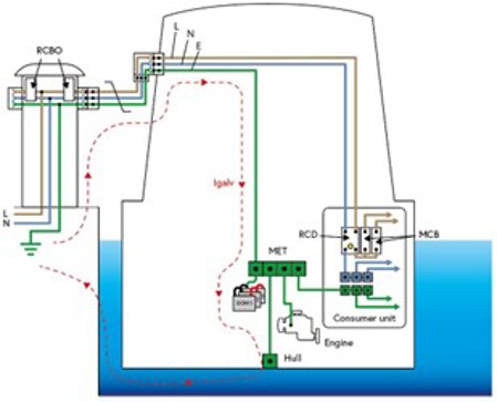
We now need to introduce a marine-environment-specific problem – galvanic corrosion. Although this phenomenon affects metal-hulled craft, its effect on GRP-hulled craft, while identical in outcome, is far less damaging. To illustrate the circumstances that can lead to the creation of a path for galvanic current (Igalv) to flow, consider a metal-hulled craft connected to a Section 709 of BS 7671-compliant 230 V AC shore-supply (Figure 3). The (Igalv) current path originates in the general mass of Earth which in turn is connected to the craft’s main earthing terminal (MET) via the shore-power PE conductor. However, because the hull is an extraneous-conductive-part, a protective bonding conductor is required between the hull and the MET. In the manner illustrated, (Igalv) will then flow via the hull back to Earth via the surrounding water.
Figure 3 Diagram illustrating potential galvanic current flow when a craft is moored close to earthed metallic structures and powered from an AC shore-supply
Clearly, while some method needs to be introduced to break the (Igalv) current path, the method employed must also preserve automatic disconnection of supply (ADS) in the event of a fault. One of two methods is generally employed: firstly, a diode-based galvanic isolator can be inserted into the PE conductor, or alternatively, an on-board isolation transformer can be used to break the PE conductor path. However, to preserve the required ADS functionality, an N-E link (‘local earth’) will be required on the output of the transformer secondary (see Figure 4). Note that the illustrated configuration features an ISO 13297-compliant reverse polarity indicator.
Figure 4 AC shore-supply with an isolation transformer employed to galvanically isolate the craft’s AC distribution system from the TN-S shore-supply
![]()
Now that we’ve introduced means to minimize the effects of galvanic corrosion attributable to the shore-power connection, we need to address the problem that arises when non‑compliant polarity correct indicators are fitted - which is leakage current.
As previously mentioned, polarity correct indicators are connected between the line and PE conductors thereby providing a leakage path to Earth via the hull and the surrounding water. While this current will be small, its presence will accelerate erosion of any cathodic protection (anodes) fitted to the boat. To eliminate this problem, an appropriately rated momentary press switch can be fitted in line with the indicator.
If you wish to dig deeper into the world that exists at the other end of a boat’s shore-power cable, pre-order a copy of the soon-to-be-published: IET On-Board Guide to Electrical Safety for Small Craft.