
High Protective Conductor Currents in Electrical Installations
Introduction
Historically, protective conductors were only required in electrical installations as a means of providing shock protection to metallic (Class I) equipment, in combination with automatic disconnection of supply.
Such protective conductors, often referred to as ‘earthing conductors’, if designed correctly would provide a low impedance path between typically an item of equipment and the earthing terminal at the installation’s origin.
Should a fault develop making any exposed conductive part of the equipment live, the low impedance path to earth, would enable a current to flow, which in a correctly designed system would enable a protective device, such as fuse or circuit-breaker to operate. This would therefore automatically disconnect the supply and remove the shock hazard.
Such conductors in these circumstances would only carry a current during fault conditions.
This philosophy is still unchanged in BS 7671:2018+A2:2022, the current version of the standard.
However, with the advent and development of equipment containing electronics, which now forms the vast part of almost all electrical installations, protective conductors are called upon to provide an additional role; a role which in many cases will result in current flow in these conductors under normal operating, non-fault conditions.
Many readers will have heard the term ‘functional earthing’ which is where a piece of equipment needs a permanent functional connection to earth in order to operate correctly as well as safely. Very often this is to allow by-products of electrical or electronic noise filtering or power conversion processes to safely dissipate energy to earth. Generally the functional earth and protective earth are the same conductor.
Where the protective conductor path may become disconnected, thereby losing its effectiveness, these functional earth currents may have nowhere to flow, and may cause any exposed conductive parts of equipment on the circuit to rise in potential with respect to true earth – paradoxically posing a shock hazard.
BS 7671 first introduced measures to deal with these ‘high protective conductor currents’ as they are known, in the 1994 amendment to BS7671:1992 and in those days dedicated a ‘special locations’ section, Section 607, to it.
As usage of equipment generating such currents increased, it became apparent that the requirement should no longer be thought of as a ‘special location’ – with consequently, the requirements being embodied in the main text of BS 7671.
High protective conductor currents may often be experienced wherever electronic equipment containing switched mode power supplies, variable speed drives, lighting control and dimming, as well as audio/visual or communications and technology equipment exists. Product standards relating to the manufacture of domestic appliances in the UK generally allow an upper limit of 3.5mA protective conductor current to such items.
This needs careful assessment at design stage, particularly the cumulative effects – not only for known existing equipment, but also the likelihood of future needs.
Where do measures against high protective conductor currents need to be considered?
BS 7671:2018 +A2:2022 requires special measures to be adopted, where either:
- an individual item is to be connected having a protective conductor current exceeding 10 mA; or
- cumulative protective conductor currents exceeding 10 mA may exist in final or distribution circuits.
Equipment manufacturers should be consulted to ascertain this information.
Guidance on the levels of expected protective conductor current can be found in clause 13.2 of BS EN 60335-1:2012+A15:2021 Household and similar electrical appliances – Safety – Part 1: General requirements.
For information and telecommunications technology equipment, maximum allowable protective conductor currents are specified in clause 5.7.5 of BS EN 62368-1:2014+A11:2017 Audio/video, information and communications technology equipment – Part 1: Safety requirements.
In order to mitigate the risk of the protective conductor becoming broken or disconnected, BS 7671 recognises two approaches on circuits where high protective conductor currents may exist:
- a larger conductor than that required for shock protection and thermal performance alone – to offer increased physical strength – particularly at terminations; and
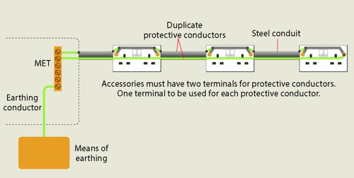
- duplicated separate conductors.
Fixed equipment
Although BS EN 62368-1 applies to the manufacture of audio/video & information and telecommunications technology equipment, it does specify minimum sizes for mains supply flexible cables to such items, which can be used as a reference.
BS 7671:2018+A2:2022 however, in regulation 543.7.1.202, requires a single item of equipment in which the protective conductor current exceeds 10 mA to be either:
- permanently wired in, with a protective conductor sized as per regulation 7.1.203;
- connected via a plug and socket outlet complying with BS EN 60309-2 (colloquially known as a ‘Commando’ type plug) with a protective conductor in the flexible cable of cross-sectional area (csa) not less than 2.5 mm2 for plugs rated at 16 A, and not less than 4 mm2 for plugs rated above 16 A; or
- connected with a protective conductor complying with the ‘normal’ requirements of Section 543 of BS 7671 but in combination with an earth monitoring system complying with BS 4444.
Regulation 543.7.1.203 stipulates requirements for final or distribution circuits, where the total protective conductor current is likely to exceed 10 mA. It requires one or more of the following:
- A single protective conductor, meeting regulations 543.2 (relating to conductor type) and 543.3 (relating to preserving electrical continuity), having csa of not less than 10 mm2 (to give a mechanically robust connection).
- A single protective conductor, meeting regulations 543.2 and 543.3, having csa of not less than 4 mm2 being enclosed, for example in a conduit, to provide additional protection against mechanical damage.
- Two individual protective conductors, meeting the requirements of Section 543.to give a duplicated conductor path. These could be of different types (for example copper conductor run in an earthed metallic conduit).
Where the two individual protective conductors are run within a multicore cable, the total csa of all the conductors - including the line and neutral conductors - shall be not less than 10 mm2. - An earth monitoring system to BS 4444, which automatically disconnects the supply if a continuity fault occurs in the protective conductor.
- Connection of the equipment to the supply by means of a double-wound transformer or equivalent unit, with the protective conductor of the incoming supply being connected to the exposed conductive parts of the equipment and to a point of the secondary winding of the transformer. The protective conductors between the equipment and the transformer will need to comply with one or more of the arrangements described in the preceding four bullet points.
Circuits serving socket outlets
These type of circuits are probably the most commonly occurring to be serving equipment producing protective conductor currents, regardless of whether within residential or non-residential properties.
For any final circuit with a number of socket-outlets or connection units intended, or considered likely, to supply several items of equipment where it is probable that the cumulative protective conductor current may exceed 10 mA, high integrity protective conductor connections complying with regulation 543.7.1.203 are needed.
Ring Final Circuits
Where a standard ring final circuit is employed, complying with Appendix 15 of BS 7671 (using typically 2.5 mm2 live conductors and 1.5 mm2 cpcs) it can be appreciated that the total csa of all of the live and protective conductors will easily exceed 10 mm2 – hence satisfying regulation 543.7.1.203.
Spurs however to the ring, will need special consideration and their own high- integrity protective conductor connections complying with regulation 543.7.1.203.
Radial Circuits
A radial circuit will pose more of a problem, since by definition it will only have one protective conductor.
Regulation 543.7.2.201 now permits either of the following arrangements:
- The protective conductor being connected as ring. In practice this will necessitate a separate protective conductor being taken from the last socket-outlet on the circuit back to the distribution board.
NOTE - To reduce interference effects, the duplicated protective conductor should be run with, or in close proximity to, the other conductors of the circuit. This is also a requirement of regulation 6.1, as it should be remembered that the duplicated protective conductor could feasibly act also as a path for fault protection currents. - A separate protective conductor being provided at the final socket outlet by perhaps connection to metal conduit, trunking or other metalwork that fulfils the requirements for a protective conductor.
Figure 1: Radial circuit with separate duplicated protective conductor
Labelling
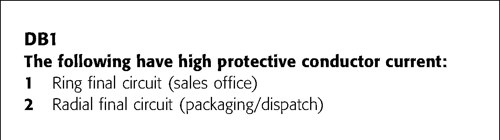
Although BS 7671 has no requirements for labelling the actual outlets or sockets serving equipment with high protective conductor currents, it does require information to be provided at the distribution board serving such circuits.
Regulation 543.7.1.205 requires relevant information to be visible to any person who may be modifying or extending such circuits. Regulation 514.17 requires this warning notice to be provided and as it is a warning and not just for information, it must be installed on the consumer unit or distribution board.
Figure 2: Example of a label affixed near a distribution board that serves circuits with high protective conductor currents
Practical considerations and best practice
Dual terminations at accessories
Although no longer a specific requirement of BS 7671:2018 +A2:2022, the practice of terminating cpc conductors separately, using wiring accessories with dual earth terminals, ought to be considered as good practice by designers and installers.
Such wiring accessories, particularly socket outlets to BS 1363, now feature in the majority of wiring accessory reputable manufacturers’ ranges, and no longer carry the premium cost that they once did.
Figure 3: Typical twin 13A BS 1363 socket with dual earth terminals
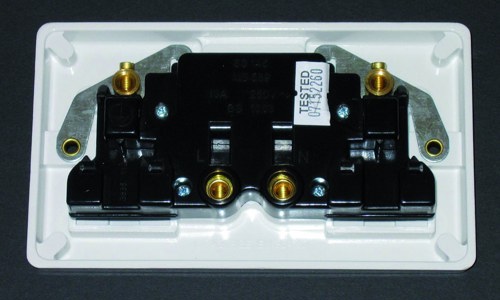
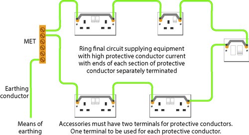
Figure 4: Typical ring final circuit, showing good practice of terminating cpcs on separate terminals
Protective conductors run individually
Where protective conductors are run separately, perhaps as a solution to deal with radial circuits or spurs to ring final circuits, consideration needs to be given to the physical strength and hence resilience of such conductors, as well as the conductor’s ability to carry fault protection currents.
The designer/installer should also consider Regulation 543.1.1, where minimum cross-sectional areas are stipulated. Notably, where a conductor is run without mechanical protection or as an integral part of cable, it shall be 4mm2. This, as can be appreciated, results in a stranded conductor which is less likely to break or snap off at terminations, compared with a solid conductor.
Other issues to consider – unwanted tripping of RCDs
Unwanted tripping of RCDs is a phenomenon that is likely where such devices protect circuits with high protective conductor currents. This risk is more likely on circuits serving socket-outlets, where the designer/installer may not know exactly the usage pattern or loadings posed by the end users.
Arguably, such circuits are also likely to serve multiple items of equipment with relatively low load, albeit capable of cumulatively generating relatively high protective conductor currents.
Regulation 531.3.2 makes specific reference to this, emphasizing the fundamental requirement to divide the installation into several final circuits.
Of note, this regulation requires that the accumulation of such currents downstream of an RCD or RCBO should not exceed 30 % of the rated residual operating current of the device. With the common need for 30 mA RCD protection, this effectively limits the earth leakage current to less than 10 mA per device.
It should also be noted that under the product standards for RCDs and RCBOs, (commonly to BSEN 61008 series and BSEN 61009 series), such a device may operate at any residual current in excess of 50 % of its rated residual operating currents.
The regulation also now requires consideration of the use of RCBOs (as opposed to grouped circuits on a single RCD) for use in residential buildings as a measure to mitigate the effects of unwanted tripping and minimize inconvenience.
Summary
High protective conductor currents are now common place due to much of the electronic equipment now in use. As a consequence, the need to consider the hazards posed is a must.
In many cases, careful consideration by the designer and simple workmanship issues can achieve compliance with the requirements of BS 7671:2018+A2:2022, often without incurring additional cost.
With circuits supplying socket-outlets in any building type, where final equipment type and usage is unknown, arguably applying the techniques outlined in this article ought to now be considered the norm.