
How embedded solar PV can affect the power factor of an installation
In 2024, the UK saw the installation of over 1 gigawatt-peak (GWp) of solar photovoltaic (PV) capacity, increasing the cumulative total to more than 17 GWp by year-end1. As solar PV systems become increasingly common, their influence on grid stability and power quality becomes increasingly important. A key consideration is the impact of commercial and industrial PV systems on power factor, a critical parameter that affects the efficiency of power distribution. This article examines how embedded solar PV generation influences power factor in commercial and industrial settings, the challenges that may arise, and potential mitigation strategies to ensure optimal electrical system performance.
Solar PV deployment
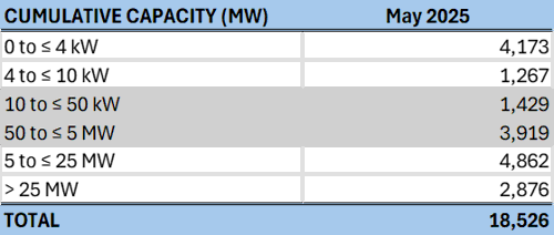
Table 1 presents the cumulative capacity of solar PV installations in the UK as of May 2025, broken down by system size. Historically, systems up to 4 kWp were classified as part of the domestic market (row 1), although these systems have been increasing in capacity. Commercial and industrial embedded systems typically range from 10 kWp up to several MWp (rows 3 and 4). By this classification, commercial and industrial solar PV accounts for approximately 29% of the UK’s total installed solar PV capacity.
Table 1 Total solar PV deployment in the UK, reproduced from Department for Energy Security and Net Zero, May 2025 National Statistics
Power factor
Power factor (PF) can be seen as a measurement, or representation of the efficiency of an electrical system. Having a poor power factor can attract reactive power charges from an energy supplier.
Power factor is represented as a unit-less number, from 0 to 1, and will be stated as leading or lagging. It can also be represented as +1 to -1, such as within control software. Formula 1 shows power factor is a ratio between active and apparent power.
Formula 1 Power factor

A system with a power factor of 0 would consume only reactive power. Conversely, a system with a power factor of 1 would consume only active power. Therefore, a power factor of 1 is a representation of the most efficient system. Anywhere between 0 and 1 and the system is consuming a mix of active and reactive power; this is termed apparent power. The term leading or lagging refers to the position of the current waveform in relation to the voltage waveform. From the view of a load, where current lags voltage, the system is inductive. From the same viewpoint, the system would be capacitive if the current leads the voltage. Therefore, a lagging power factor is inductive whereas a leading power factor is capacitive.
A frequent cause of poor power factor in electrical installations is the use of motors without any form of power factor correction. Motors introduce inductive reactance, which results in a lagging power factor if not properly compensated
The three types of power that are referred to in this article are included in Table 2, which also includes the corresponding symbol, unit, and some of the common formulae for determining their values.
Table 2 Types of power
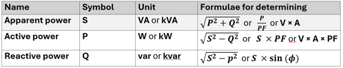
Where PF is cos (ϕ), and ϕ is the phase angle.
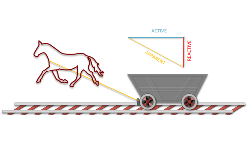
Figure 1 provides an analogy to help explain power factor. While the horse moves forward to pull the carriage, there is also a force acting at a right angle to the direction of travel. This sideways force requires the horse to exert more power than if it were pulling straight ahead. In this analogy, the forward movement represents active power, the force acting at a right angle represents reactive power and together they combine orthogonally to form apparent power.
Figure 1 Horse and carriage power factor analogy
Apparent power is the product of the voltage multiplied by the current with no consideration for the phase angle between the two.
Active power is the power that carries out work and accounts for the phase angle between the voltage and current.
Reactive power is power that is transferred back and forth from the supply and load and does no direct work.
Power factor load vs generator
When describing a load, a leading capacitance typically cancels out a lagging inductance, and vice-versa. However, this terminology changes when referring to a generator supplying or consuming reactive power.
Specifically, when a generator supplies reactive power to the load, it is said to have a lagging power factor. Conversely, when the generator absorbs reactive power, it is described as ‘leading’.
Figure 2 represents a phasor diagram with multiple current phasors (I1- I4), using the voltage as the reference phasor (at 0o). The current phasors are described as follows:
- I1: Current of a capacitive load with a 0.96 leading power factor
- I2: Current of a generator with a 0.96 lagging power factor
- I3: Current of a generator with a 0.96 leading power factor
- I4: Current of an inductive load with a 0.96 lagging power factor.
Figure 2 Phasor diagram

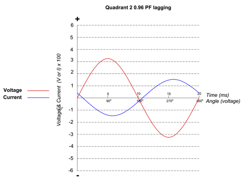
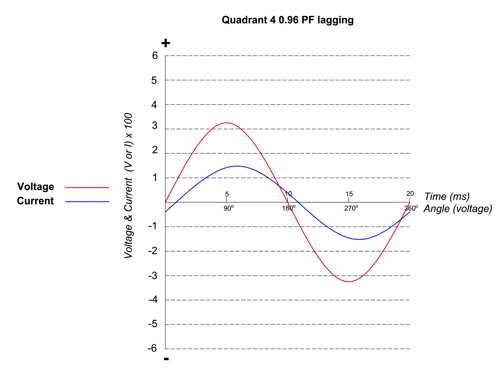
A generator operating at a 0.96 lagging power factor (quadrant 2, I2) can supply the reactive power (vars) required by a load with a 0.96 lagging power factor (quadrant 4, I4), providing the currents are of equal magnitude.
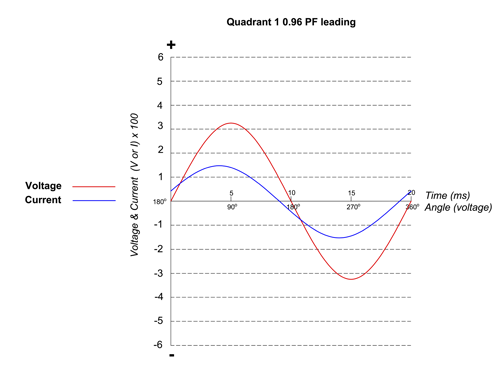
Each of the currents (I1- I4) are also represented in Figure 3 as waveform diagrams to illustrate the leading and lagging behaviour of the currents.
Figure 3 Waveform diagram representing the four quadrants

How does a PV system affect the power factor of an installation?
PV systems have been in use for many years, with their popularity increasing following the introduction of the Feed-in-Tariff (FIT) under the Energy Act 2008. The FIT scheme provided financial incentive to owners of small-scale generators. This was based on the amount of energy they produced, measured in kilowatt-hours (kWh). This incentivized PV system owners to generate only active power (kW) rather than a mix of active and reactive power (kVA).
Although the FIT scheme closed in 2019, PV systems are still commonly marketed based on their estimated kWh savings, as this aligns with the electricity billing unit most consumers are familiar with. Furthermore, the smart export guarantee (SEG) scheme introduced in 2020 is based on a unit of kWh, as is energy brokering that is common with larger PV systems.
The ability of PV systems to provide reactive power may be sometimes overlooked. Reactive power in a PV system is provided by the inverter; this is achieved by the inverter controlling the amplitude of the output voltage relative to the grid voltage—raising the voltage to export (supply) reactive power and lowering it to import (absorb) reactive power.
To understand how a PV system affects the power factor of an installation, it is best to first look at how the apparent, active and reactive energy consumption is determined.
If, at a point in time, an installation is using 100 kW, and 104 kVA, the power factor at this point in time is:
Equation 1

PF = 0.96 (to two significant figures)
For simplification, if this installation had this as a steady load for 8 hours per day, 5 days per week, the energy usage for a five-day working week would be:
Equation 2
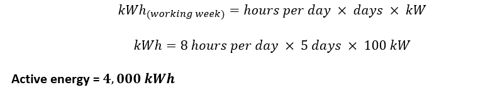
Equation 3
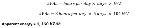
Equation 4
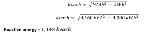
The reactive energy use can be calculated as follows:
If a PV system is now introduced into the electrical installation and is configured to deliver only active power (kW) to maximize a tariff such as the FIT or SEG, this would influence the amount of energy delivered by the grid.
If, over the course of a week, the PV system generated 1,200 kWh of energy, how would this impact the power factor of the system as observed by the energy supplier?
From the energy supplier’s perspective, there would be a reduction of 1,200 kWh in active energy consumption, but no decrease in reactive energy demand.
Equation 5
![]()
As per Equation 5, the active energy delivered to site from the energy supplier would be 2,800 kWh, while the reactive energy required would remain at 1,143 kvarh. The new power factor, as observed from the energy supplier, can be calculated as follows:
Equation 6

Equation 7

PF = 0.93 (to two significant figures)
With the new values, the PV system has negatively impacted the installation’s power factor as seen from the supplier, reducing it from 0.96 to 0.93. This, in turn, lowers its efficiency from the perspective of the energy supplier.
This effect can become more pronounced when a large PV system is installed to supply most of the on-site power during the summer months, while the installation continues to rely on the grid for reactive power.
Visualized
Figure 4 illustrates the power factor triangles of the installation shown from the energy supplier’s perspective, across three distinct stages:
- Before the PV system is added
- With the PV system added operating at a PF of 1
- With the PV system added operating at a PF matching the load.
Figure 4 Power factor impact visualized


Figure 4 demonstrates that upon integrating the PV system without reactive power support, the phase angle (Φ) increases from its original value. However, once the inverter's power factor is adjusted to match the load, the phase angle returns to its initial position.
Is this a problem?
Where an electrical supply is metered at half-hourly rates, which is commonly carried out on commercial and industrial installations, suppliers and distribution network operators (DNOs) may charge for what they deem to be excessive reactive power usage. A common methodology for applying this charge is where the power factor of an installation averages below 0.95 for a half-hour period. With this methodology, reactive charges are applied to any units of kvarh exceeding 33 % of the kWh usage.
In the earlier example, no reactive power charges applied before the PV installation, as the power factor was greater than 0.95. Post-installation, the power factor fell to 0.93, which could lead to the introduction of reactive power penalties.

How are the additional charges calculated?
If the reactive power charge was based on reactive units over the 33 % threshold, the installation would incur additional charges on the reactive energy used above this threshold.
This can be calculated as follows:
Units used in a five-day period:
2,800 kWh
1,143 kvarh
Determining the 33 % threshold for charges:
2,800 kWh x 0.33 = 924 units
Units to be billed:
1,143 kvarh – 924 = 219 kvarh
A payment would be due for 219 kvarh units. The cost per unit of kvarh can be much higher than the standard unit rate of kWh.
Although no additional reactive power is used with the introduction of the PV system, the installation will incur charges for some of the reactive power consumed, as the power factor has fallen below the threshold where reactive charges are applied.
DNO specifications for PV generator connection
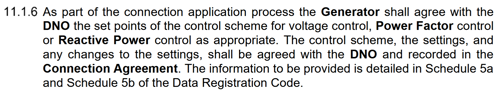
When connecting a PV system to the grid for parallel operation, compliance with Engineering Recommendation G98 (for systems ≤16 A per phase) and Engineering Recommendation G99 (for systems >16 A per phase) is generally required. These recommendations mandate that the inverter has a specified power factor operating range and may also require the PV inverter to provide reactive power control. Relevant excerpts from these documents include:
Figure 5 9.5.1 of EREC G98 Issue 1 Amd 7: Oct 2022
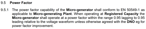
Figure 6 11.1.5 of EREC G99 Issue 1 AMD 9: OCT 2022
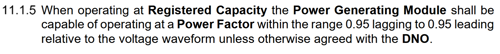
Figure 7 11.1.6 of EREC G99 Issue 1 AMD 9: OCT 2022
Can reactive power charges be avoided?
To conform to the engineering recommendations, the inverter must have a specified power factor operating range. This range requires the inverter to either produce or consume reactive power.

As stated earlier, from a generator’s perspective, power factor is the inverse of that of a load. When a generator produces reactive power, it is considered lagging, therefore, to counteract a load’s lagging power factor, the inverter is configured to provide a lagging power factor.
In the earlier example, the inverter’s threshold can be set to match the power factor of the load, which was 0.96 lagging. By configuring the inverter to a power factor of 0.96 lagging, the overall system’s power factor, as seen by the energy supplier, remains unchanged.
This is a simplified explanation for understanding, although in practice, an installation's power factor can fluctuate throughout the day depending on the usage of connected loads. However, some inverters can dynamically adjust their power factor set point to match that of the load.
It is worth noting that the power factor of the installation should be measured before the PV system is installed. A PV system should not be used as a remedy for poor power factor; instead, power factor correction should be implemented where necessary. Achieving an efficient system with a power factor of at least 0.95, thus avoiding punitive reactive power charges, may be a good starting point.
Would this reduce the active power output of the PV system?
Inverters are power electronic devices; many modern models can supply reactive power without reducing active power output. This can be conditional on the apparent power (kVA) staying within the inverter's maximum capacity.
If there is no available kVA headroom (the difference between the kVA output from the PV system and the maximum kVA of the inverter), the active power output will be reduced to accommodate the required reactive power. This can be in times of high irradiance where the PV array is oversized relative to the inverter. Where reactive power is to be supplied by the inverter, the designer may consider increasing the capacity (kVA) of the inverter. However, this needs to be weighed against any potential efficiency losses.
When sufficient headroom is available, active power can remain unaffected, ensuring the installation's power factor, as seen by the grid, is maintained.
Some PV inverters can provide reactive power support even when there is no generation from the PV modules, such as at night.
Are there any other consequences from providing reactive power through an inverter?
If the inverter’s power factor setting is stationary, and not dynamically controlled, there is a possibility of voltage rise at the connection point at times when the load is minimal but generation is high (system exporting). This could be problematic where an installation’s voltage is near the statutory limits, as the PV system could push the voltage level over the statutory threshold. An inverter’s maximum permitted output voltage is typically higher than the permitted voltage range of the grid supply. One of the consequences of this is O-PEN detection devices disconnecting electric vehicle (EV) chargers where their upper limit is 253 V between line and neutral. However, O-PEN devices built to the IET 01:2024 Open combined protective and neutral (PEN) conductor detection devices (OPDDs) standard may still operate, as this standard permits the manufacturer to have an increased voltage trip threshold where additional protection methods are employed from this standard.
The performance of other products developed according to BS EN 60038 CENELEC standard voltages may also be affected as a result of long-term voltage in excess of 253 V. In addition, some product standards specifically have verification (type test) requirements that are limited to verifying the operation of the product for a utilization voltage range of 0.85 U0 to 1.1 U0 (or 0.85 U to 1.1 U for three-phase, three-wire equipment).
What about domestic PV systems?
The focus of the article has been on commercial and industrial PV systems as reactive power charges are generally applied to these sectors where half-hourly metering is employed. Engineering Recommendation G98, which covers generating sets up to 16 A per phase (which are commonly used in domestic installations), includes an operating range for the power factor of the inverter (see Figure 5). However, it states the power factor may be agreed upon separately with the DNO. The DNO may impose a specific power factor setting in areas of the network with poor power factor or where voltage rise is an issue. Each of these scenarios would require a different inverter configuration. Typically, a domestic PV system installer needn’t worry about the power factor setting of an inverter.
Summary
Traditional solar PV systems were designed to maximize active power generation, often neglecting reactive power. Since power factor is a measure of the efficiency of electrical systems, a poor power factor can result in additional charges for reactive power. To address this, engineering recommendations such as G98 and G99 require PV inverters to have a power factor operating range.
Some modern inverters can dynamically adjust their power factor to match the load, preventing efficiency losses and avoiding reactive power charges. Providing there is sufficient headroom for the required reactive power, this can be achieved without sacrificing active power output. Careful design consideration shall be given to these systems, as unwittingly altering power factor settings can introduce problems, such as voltage rise.
References
- D. f. E. S. &. N. Zero, Solar Photovoltaics deployment in the UK - December 2024.
Further reading
IET 01:2024 Open combined protective and neutral (PEN) conductor detection devices (OPDDs)
Acknowledgements
- Calum Mansell
- Darren Crannis
- Graham Kenyon
- Leon Markwell
- Mark Coles
- Michael Peace.