Neutral current diversion (NCD) – industry research update
Last year, the IET set out to gain information on ‘neutral current diversion’, working with industry partners NICEIC, ECA, Electrical Safety First, NAPIT, and SELECT. To support our research, we asked electrical installers and inspectors to answer a series of questions upon discovery of ‘neutral current diversion’. This article presents the information received from the industry, along with a commentary on the results.
What was the most common earthing system reported?
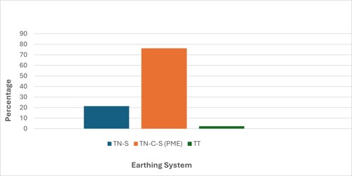
The TN-C-S protective multiple earthing system (PME) was the most common form of system recorded approximately 76 % of the time, followed by the TN-S system at 22 %, and the remaining 2 % being TT systems (see Figure 1).
Figure 1 Most common earthing systems reported
It is widely accepted that the TN-C-S (PME) system is provided for new installations. A cable which contains phase conductor(s) and a combined protective earth and neutral conductor is used within the distributor’s network. This combined conductor is used for the protective earthing and neutral functions and is known as the protective earthed neutral (PEN) conductor.
Whilst BS 7671, Requirements for Electrical Installations1, “Part 2 Definitions”, refers to the term ‘PEN conductor’, it is common for Distribution Network Operators (DNOs) to use the term combined neutral and earth (CNE) cable. Neutral current diversion (NCD) occurs where the PEN conductor is broken.
Prior to the introduction of PME, the network cable of choice was the separate neutral earth (SNE) cable. However, SNE cables in the network have become increasingly rare due to modifications, fault repair and the increase of CNE cables installed within sections of the network. The Energy Networks Association (ENA) provides guidance on PME networks in the form of the Engineering Recommendation G12, Requirements for the Application of Protective Multiple Earthing to Low Voltage Networks, Issue 5, 20232 and references the term ‘hybrid network’ where SNE (TN-S) cables were originally installed and, over time, CNE cables have been inserted. The TN-S system requires a continuous earth connection all the way back to the supply transformer; however, with the rise in the number of hybrid networks, it could be argued that very few TN-S systems exist in the public distribution network.
Recognizing this, the IET Code of Practice for Electric Vehicle Charging Equipment Installations, 5th Edition3, has advised designers to treat TN-S systems as TN-C-S (PME) unless it can be guaranteed that the TN-S system extends back to the supply transformer and will not be modified in the future. An example of this could be where a TN-S system is supplied by a private transformer.
Where older installations may have been converted from a TN-S to TN-C-S (PME) system, the cross-sectional area of any main protective bonding conductors should be verified as suitable for continued use. This is due to older installations often having smaller main protective bonding conductors in situ; this, coupled with the risk of open PEN conditions in TN-C-S (PME) systems, may increase the risk of thermal damage to conductors.
While the amount of TT systems recorded was low, it is important to consider that in the event of an open PEN conductor, voltage could appear on a TT system. Designers are therefore required to maintain separation below ground between earth electrodes and buried conductive parts connected to TN-C-S (PME) systems. Local DNOs may have specific requirements for maintaining separation, which should be confirmed before installation. For additional guidance, see BS 7340:2011+A1:2015 Code of practice for protective earthing of electrical installations4, which contains information on potentials around earth electrodes.
What method was used to determine neutral current diversion?
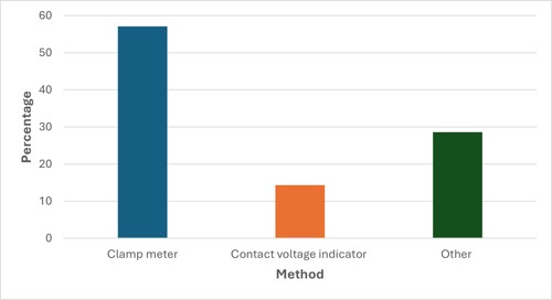
The application of a clamp meter, both before and after isolation of the installation, provides a useful check of any current flowing in the earthing conductor and the main protective bonding conductor(s) while identifying changes in load. Approximately 57 % of those who responded utilized a clamp meter to determine NCD, a method identified in Table D1 of the IET’s Guidance Note 3: Inspection & Testing, 9th Edition5, followed by 14 % who used a contact voltage indicator. Other methods included the use of multimeters, data loggers and visual signs of arcing, making up the remaining 29 % (see Figure 2).
Figure 2 Method used to determine neutral current diversion
One respondent reported they were first alerted to the possibility of current diversion due to sparks on the gas service installation pipework when verifying the continuity of conductors (test method 2) with the installation isolated.
Within older electrical installations, extraneous-conductive-parts often take the form of metallic water and gas installation pipework, as opposed to the modern-day preference of plastic. In the case of an open PEN conductor, the path the current takes is effectively determined by the load and impedance on the network. Extraneous-conductive-parts offer low impedance paths for neutral current to flow, potentially resulting in a significant heat build-up that can lead to fires and gas explosions.
Another respondent reported that the current recorded at the installation they were working at was subsequently found to have originated from an adjoining installation. This is a general theme of the comments and highlights that NCD can affect multiple installations at a time.
What was the average voltage/current measured?
In 67 % of cases, respondents found an unexpected voltage that first highlighted NCD. The average current measured through the earthing conductor and/or extraneous-conductive-parts was 12 A, while the highest current recorded was 67 A.
As mentioned earlier in the article, the path taken by the current is effectively determined by the impedance of each available path and the load on the network at a given time. This is validated by the comments provided by a respondent, in which they report there was little to no current at the point of beginning the work. However, as the work progressed, a load was added to the installation next door, which resulted in 43 A being recorded at the installation being worked upon.
Precautions should be taken when disconnecting any earthing and protective bonding conductors. Where an open PEN conductor exists, the removal of the earthing conductor or protective bonding conductors can cause hazardous touch voltages to appear on extraneous-conductive-parts and exposed-conductive-parts.
Table D1 of the IET’s Guidance Note 3: Inspection & Testing, 9th Edition, confirms that a non-contact voltage indicator, commonly referred to as a volt-stick, can be utilized to check for voltage at extraneous-conductive-parts, as well as the main earth terminal, the earthing conductor and the main protective bonding conductors. It is important to remember that a non-contact voltage indicator is a proximity device and should not be used for proving equipment as dead; however, it can be useful in identifying live equipment.
It is not just electricians who are noticing the effects of NCD. Information provided by another respondent attending an emergency call-out following a gas engineer reporting “sparks on the gas installation pipework when a nut was undone” recorded 3.9 A present. The gas industry has produced information and guidance relating to safe-to-touch and safe isolation for gas engineers when carrying out gas work – The Gas Safe Register, Technical Bulletin (TB) 118a, Safe to touch and/or safe isolation and proving electrically dead on low voltage single-phase supplies (below 1000 volts), Feb 20236. The process of ‘safe-to-touch’ is a custom practice within the gas industry, where a non-contact voltage indicator is used to ensure a hazardous touch voltage is not present due to a fault condition by touching appliance casings, gas and water installation pipework. Additionally, Network Rail has provided all electrically and non-electrically trained members of staff with non-contact voltage indicators to check for any potentially dangerous voltages.
Did all respondents contact the DNO following the identification of neutral current diversion?
The percentage of respondents who reported the incident to the respective DNO was around 49 %, with the DNO attending in all but one of those cases.
Regulation 114.1 of BS 7671 states that for a supply provided in accordance with the Electricity Safety, Quality and Continuity Regulations (ESQCR), “it shall be deemed that the connection with Earth of the neutral of the supply is permanent.” DNOs have responsibilities under the ESQCR, which is a statutory document.
It should be remembered that NCD can cause hazardous touch voltages to appear on the extraneous-conductive-parts and exposed-conductive-parts of the installation, as well as fire, explosion and damage to electrical equipment. Therefore, the IET and our industry partners strongly advise anyone who suspects NCD is present to report without delay to their local DNO by calling 105 (see Figure 3).
Figure 3 Map of the UK and Ireland’s distribution network operators

Where was neutral current diversion reported?
The results have highlighted parts of the UK with significantly higher occurrences of NCD, for example, the Midlands and the South East of England; however, no significant volumes of NCD were reported in Wales, Northern Ireland and the North of England (see Figure 4). The rationale behind obtaining the location of NCD is to identify patterns of occurrence, be that in a specific part of the UK, DNO or several incidents within the same postcode region.
Figure 4 Map of the UK indicating where neutral current diversion was reported

While we have received a great deal of information regarding NCD incidents from industry, we feel that additional information would only benefit our research; therefore, we have decided to leave the survey open at this point to continue our investigation.
How do I report neutral current diversion?
Should NCD be detected, we ask that you submit your findings via our online form where you will be presented with a number of simple questions.
Acknowledgments
- Craig O’Neill
- Frank Bertie
- Leon Markwell
- Luke Osborne
- Michael Peace
Further information
- IET Guidance Note 3: Inspection & Testing, 9th Edition
- IET Wiring Matters “Broken PEN” (Issue 84, March 2021)
- IET Wiring Matters “Neutral current diversion (NCD) - industry research” (Issue 101, July 2024)
References
- BS 7671 Requirements for Electrical Installations, IET Wiring Regulations, Eighteenth Edition
- ENA Engineering Recommendation G12, Requirements for the Application of Protective Multiple Earthing to Low Voltage Networks, Issue 5, 2023
- IET Code of Practice for Electric Vehicle Charging Equipment Installation, 5th Edition
- BS 7340:2011+A1:2015 Code of practice for protective earthing of electrical installations
- IET Guidance Note 3: Inspection & Testing, 9th Edition
- Technical Bulletin 118a Safe to touch and/or safe isolation and proving electrically dead on low-voltage single-phase supplies (below 1000 volts)
- Who’s my electricity network operator? – Energy Networks Association (ENA)