Integration of devices and components
A question that is often asked relates to the issue of whether mechanical and electrical devices, and other such components from one manufacturer, can be integrated into existing low-voltage assemblies from a different manufacturer. This article looks at the issues associated with using electrical devices and components, such as surge protective devices (SPDs), which may not have been specifically declared as suitable by the assembly manufacturer.
What are low-voltage switchgear and controlgear assemblies?
The BS EN 61439 and BS EN IEC 61439 series provide requirements for low-voltage switchgear and controlgear assemblies. Examples of such equipment include consumer units, distribution boards and panel boards. BS EN 61439-3 includes requirements for assemblies that are commonly products referred to as consumer units (CUs) which this article generally focusses upon.
For the purposes of this article, the relevant clauses of the following apply:
- BS EN 61439-1:2011 and BS EN IEC 61439-1:2021 Low-voltage switchgear and controlgear assemblies. General rules.
- BS EN 61439-3:2012 and BS EN IEC 61439-3:2024 Low-voltage switchgear and controlgear assemblies. Distribution boards intended to be operated by ordinary persons (DBO).
What devices and components can be integrated into low-voltage switchgear and controlgear assemblies?
Examples of devices and components that can be integrated into low-voltage switchgear and controlgear assemblies include circuit-breakers, control devices, timers and SPDs. Most manufacturers offer consumer units and distribution boards that come complete with SPDs. However, some manufacturers also offer standalone devices.
What are the requirements of BS 7671 for integration of devices and components?
Regulation 536.4.203 of BS 7671:2018+A2:2022+A3:2024 provides requirements for integration of mechanical and electrical devices and components as below:
The relevant part of the BS EN IEC 61439 series shall be applied to the integration of mechanical and electrical devices and components, e.g. circuit-breakers, control devices, busbars into an empty enclosure or existing low voltage assembly.
In low voltage assemblies to the BS EN IEC 61439 series, e.g. consumer units, distribution boards, incorporated devices and components shall only be those declared suitable according to the assembly manufacturer’s instructions or literature.
What are the particular points embodied in Regulation 536.4.203?
Two key points to address are:
- The practice of installing devices of one manufacturer into an assembly of another manufacturer.
- The practice of installing new or replacement devices into an existing assembly, even if both are from the same manufacturer.
The notes to Regulation 536.4.203 contain some important aspects of clarification to address common misconceptions. Below is an extract from the notes:
NOTE 1: The use of individual components complying with their respective product standard(s) does not indicate their compatibility when installed with other components in a low voltage switchgear and controlgear assembly.
NOTE 2: Incorporated components inside the assembly can be from different manufacturers. It is essential that all incorporated components should have had their compatibility for the final enclosed arrangements verified by the original manufacturer of the assembly and be assembled in accordance with their instructions e.g. the consumer unit, distribution board manufacturer. … If an assembly deviates from its original manufacturer’s instructions, or includes components not included in the original verification, the person introducing the deviation becomes the original manufacturer with the corresponding obligations.
Note 1 and note 2 are intended to be warnings, because devices are frequently type-tested and assigned ratings, for example, a thermal/current rating and short-circuit rating for unenclosed in free air. When integrated into an assembly, these free air ratings can be altered due to mutual grouping effects, ambient temperature and reduced clearances. Also, introducing a device not previously included in the verification/testing could adversely affect another device, for example, its temperature rise. This is covered later.
It is essential that guidance is sought from the original CU manufacturer regarding suitability for any addition, alteration or modification to the CU. Regulation 510.3 of BS 7671:2018+A2:2022+A3:2024 requires that every item of equipment selected and erected shall take account of manufacturer’s instructions.
Who is the original manufacturer of the CU and what are their responsibilities?
The BS EN IEC 61439 series defines the original manufacturer and makes several references, which can be summarized as:
The organization that has carried out the original design and the associated verification of the CU with the components (enclosures, busbars, circuit-breakers, etc.) and which can be assembled in accordance with the original manufacturer’s instructions in order to produce various assemblies.
The Electrical Equipment (Safety) Regulations 2016 highlights specific responsibilities of the manufacturer which include:
Before placing electrical equipment on the market, a manufacturer must ensure that it has been designed and manufactured in accordance with the principal elements of the safety objectives and labelling of electrical equipment is marked with the name, registered trade name or registered trademark of the manufacturer; and a single postal address at which the manufacturer can be contacted.
Why is it important that manufacturers verify equipment that is integrated into a CU?
Using a spare way of a consumer unit is very convenient. It is often assumed that devices and components, such as circuit-breakers and SPDs, with similar dimensions are compatible or won’t have any detrimental effects, however, this may not be the case. There are a number of safety requirements in the BS EN IEC 61439 series that the CU manufacturer must verify. Temperature rise is one key requirement.
Why are manufacturers required to verify that temperature rise limits are not exceeded?
A critical safety verification is to confirm that the temperature rise limits are not exceeded, including those for built-in components, terminals for external insulated conductors, busbars and conductors, and manual operating means.
The BS EN IEC 61439 series prescribes various methods to verify temperature rise, including testing and calculation. Calculation can be a complex method. Frequently software is used to meet PD IEC TR 60890:2022 A method of temperature-rise verification of low-voltage switchgear and controlgear assemblies by calculation. Part 0: Guidance to specifying assemblies, which is a method of temperature-rise verification. Also, temperature-rise verification by calculation in accordance with the BS EN IEC 61439 series requires additional safety margins to avoid hot spots, for example, components are de-rated.
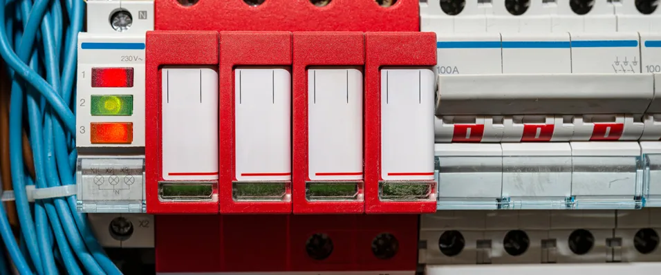
Temperature rise by testing requires thermocouples to be placed at points prescribed by BS EN IEC 61439. Some of these locations are shown in Figure 1.
Figure 1 Temperature rise testing thermocouples placed at designated points prescribed by BS EN 61439. Image reproduced by permission of Hager Group.

How can adding an unverified device create temperature rise issues?
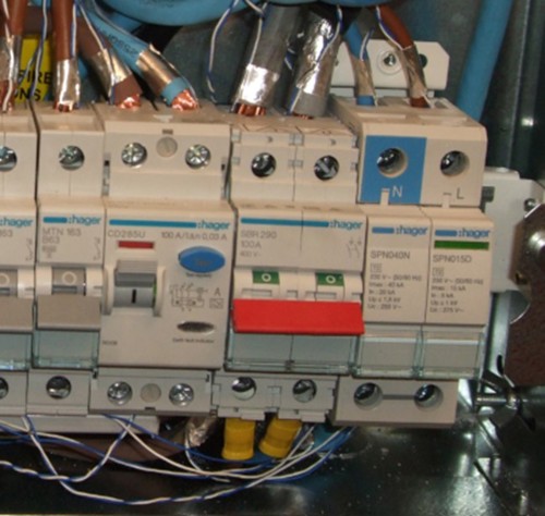
Figure 1 shows a CU under temperature rise test without any device adjacent to the main switch. If a device, for example, an SPD, was subsequently added, this would reduce the heat liberated from the main switch. Even if the SPD has minimal heat dissipation, it can insulate the side of the switch and this specific arrangement needs to be verified, as shown in Figure 2.
Figure 2 Temperature rise testing thermocouples placed at designated points with SPD adjacent to the main switch. Image reproduced by permission of Hager Group.
What other verifications are required to be carried out by the CU manufacturer?
The BS EN IEC 61439 series prescribes a number of design verifications including:
- strength of materials and parts
- degree of protection of enclosures
- clearances and creepage distances
- protection against electric shock and integrity of protective circuits
- incorporation of switching devices and components
- internal electrical circuits and connections
- terminals for external conductors
- dielectric properties
- verification of temperature rise
- short-circuit withstand strength
- electromagnetic compatibility
- mechanical operation.
Incorporation of switching devices and components, together with correct electrical connections, is critical to avoiding overheating connections and, potentially, fire.
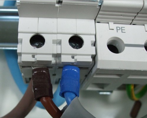
The device connections used in the original CU verification are essential to the final arrangements covered by the certification and declarations from the CU manufacturer. Figure 3 shows an example of where SPD connections do not share the same terminal opening as the main conductors but utilize the bi-connect terminals to provide a suitable electrical connection.
Figure 3 Example of where terminals use a specific arrangement for a suitable electrical connection. Image reproduced by permission of Hager Group.
It should be noted that product standards such as BS EN 60898-1 Electrical accessories. Circuit-breakers for overcurrent protection for household and similar installations - Circuit-breakers for a.c. operation, typically set limits during certain tests. Some device tested values can be close to the limits, whilst others can be significantly lower, for example, 50 % reduced power loss and 64 % reduction in energy let-through under short-circuit, than the product standard limits. This means that CU test arrangements with these devices would produce more favourable results than with devices at their product standard limits. This means that devices are not automatically interchangeable with others of similar dimensions and markings.
What if I install devices and components that have not been verified by the CU manufacturer?
If any devices and components are installed, that have not been verified by the CU manufacturer, the installer takes responsibility. It becomes the responsibility of the installer to undertake appropriate verification to ensure conformity with the relevant product standards and the low voltage directive (LVD)/The Electrical Equipment (Safety) Regulations 2016. This leaves the installer in a difficult position. This situation is explained in Note 2 of Regulation 536.4.203 of BS 7671:2018+A2:2022+A3:2024, referred to in this article.
Summary
BS 7671:2018+A2:2022+A3:2024 does not prevent mixing manufacturers, however, the arrangements must be validated.
Whilst devices and components may appear to be compatible in terms of manufacturer and dimensions, the CU manufacturer should be contacted to ensure compatibility. It is important that proof of the confirmation is obtained and it is recommended to append it to the electrical certification.
Unless devices/modifications are approved by the CU manufacturer, the simplest and safest option, is to install devices, such as circuit-breakers and SPDs, in a separate assembly. Another option is to contact the manufacturer to ask if it is permissible to add devices, such as SPDs.
Mixing devices and components in an assembly that have not been verified for such arrangements could invalidate any warranty or result in an unsafe situation. In the event of death, injury, fire or other damage, it is likely that the installer would be held accountable.
Further reading
- BEAMA technical bulletin on safe selection of devices for installation into assemblies
- GAMBICA technical guide to the requirements
Acknowledgments
- BEAMA
- Calum Mansell
- Craig O’Neill
- Gary Gundry
- Joe Cannon
- Leon Markwell
- Mark Coles
- Peter Monfort (Arena training)